Table of Contents
Advertisement
Instruction Manual
D103296X012
Fisher
2052 Diaphragm Rotary Actuator
™
Contents
. . . . . . . . . . . . . . . . . . . . . . . . . . . . . . . . .
. . . . . . . . . . . . . . . . . . . . . . . . . . . . .
. . . . . . . . . . . . . . . . . . . . . . . . . . . . . . . . .
. . . . . . . . . . . . . . . . . . . . . . . . . . .
. . . . . . . . . . . . . . . . . . . . . . . . . . . . . . .
. . . . . . . . . . . . . . . . . . . . . . . . . . . . . . . . . .
. . . . . . . . . . . . . . . . . . . . . . . . . .
. . . . . . . . . . . . . . . . . . . . . . . . . . . . . . . . .
. . . . . . . . . . . . . . . . . . . . . . . . .
. . . . . . . . . . . . . . . . . . . . . . . . . . . . . . .
. . . . . . . . . . . . . . . . . . . . . . . . . . . . . . . . . . .
Introduction
Scope of Manual
This instruction manual includes installation, adjustment, operation, maintenance, and parts information for the
Fisher 2052 diaphragm rotary actuator (figure 1). Instructions for the control valve, positioner, manual actuator, and
other accessories are included in separate manuals.
Do not install, operate, or maintain a 2052 actuator without being fully trained and qualified in valve, actuator, and
accessory installation, operation, and maintenance. To avoid personal injury or property damage, it is important to
carefully read, understand, and follow all the contents of this manual, including all safety cautions and warnings. If you
have any questions about these instructions, contact your
proceeding.
Description
2052 spring-and-diaphragm rotary actuators are used on rotary-shaft valve bodies for throttling or on-off applications.
The 2052 may be used for on-off service without a positioner, or it may be used for throttling service with a positioner,
depending on service conditions. The 2052 has an ISO 5211 mating interface that allows installation to non-Fisher
valves. Refer to separate bulletins for valve and positioner information.
A top-mounted handwheel option is available for infrequent service as a manual actuator. For repeated or daily manual
operation, the unit should be equipped with a side-mounted declutchable 1078 manual actuator. Externally adjustable
travel stops are used to limit the degree of rotation at both ends of the actuator stroke.
The lever for the 2052 actuator is supported by bushings. The lever may be changed to accommodate valve bodies
with different size valve shafts.
www.Fisher.com
. . . . . . . . . . . . . . . . . . . . . . . .
. . . . . .
. . . . . . . . .
. . . . . . . . . . . . .
. . . . . . . . . . . . . . . . . . . .
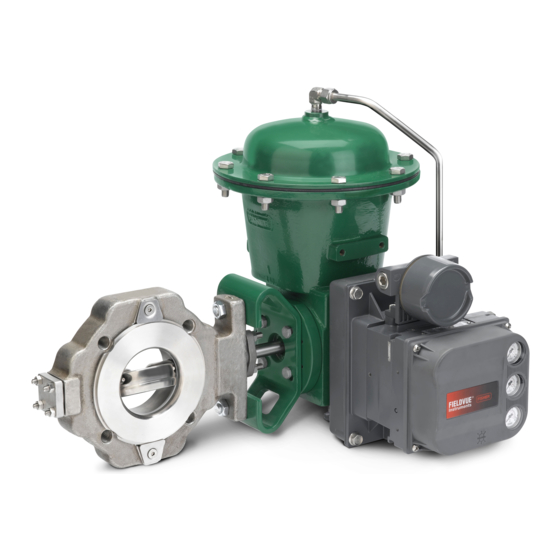
Figure 1. Fisher Control-Disk™ Valve with
2052 Actuator and DVC6200 Digital Valve Controller
1
1
1
4
4
4
5
7
8
9
11
12
12
13
17
17
Emerson sales office
2052 Actuator
or Local Business Partner before
June 2017
Advertisement
Table of Contents

Related Manuals for Emerson Fisher 2052


Summary of Contents for Emerson Fisher 2052
-
Page 1: Table Of Contents
Scope of Manual This instruction manual includes installation, adjustment, operation, maintenance, and parts information for the Fisher 2052 diaphragm rotary actuator (figure 1). Instructions for the control valve, positioner, manual actuator, and other accessories are included in separate manuals. Do not install, operate, or maintain a 2052 actuator without being fully trained and qualified in valve, actuator, and accessory installation, operation, and maintenance. - Page 2 Instruction Manual 2052 Actuator June 2017 D103296X012 Table 1. Fisher 2052 Actuator Specifications Specifications Splined shaft connection, ISO 5211 actuator‐to‐bracket connection Actuator Mounting Connections Size 1: F07, Size 2: F10, Size 3: F14 Actuator Sizes See table 2 Operating Pressure...
- Page 3 Instruction Manual 2052 Actuator D103296X012 June 2017 Table 4. Fisher 2052 Actuator Mounting Styles VALVE SERIES OR DESIGN VALVE SERIES OR DESIGN A11, 8510B, 8532, 8560, 8580, BALL/PLUG DISK/BALL MOUNTING ACTION CV500 9500, and V150, V200 & V300 ROTATION TO...
-
Page 4: Educational Services
Instruction Manual 2052 Actuator June 2017 D103296X012 Educational Services For information on available courses for Fisher 2052 actuators, as well as a variety of other products, contact: Emerson Automation Solutions Educational Services - Registration Phone: 1-641-754-3771 or 1-800-338-8158 E-mail: education@emerson.com emerson.com/fishervalvetraining... -
Page 5: Actuator Mounting
Instruction Manual 2052 Actuator D103296X012 June 2017 The actuator, as it comes from the factory, is normally mounted on a valve body. If the actuator is shipped separately or if it is necessary to mount the actuator on the valve, perform the procedures presented in the Actuator Mounting section. - Page 6 To avoid personal injury or property damage, ensure the travel indicator is installed correctly to coincide with the desired actuator action. Refer to figure 3 for more information. Figure 3. Fisher 2052 Actuator Travel Stops and Travel Indication INDICATOR ORIENTATION...
-
Page 7: Maintenance
Instruction Manual 2052 Actuator D103296X012 June 2017 7. Before sliding the valve shaft into the lever, position the valve ball or disk as follows: For push‐down‐to‐close action, the valve ball or disk should be in the fully open position. For push‐down‐to‐open action, the valve ball or disk should be in the fully closed position (see the valve body instruction manual). -
Page 8: Replacing Diaphragm
To avoid personal injury from precompressed spring force suddenly thrusting parts away from the actuator, spring compression must first be relieved. Closely follow the instructions below. Figure 4. Orientation of the Fisher 2052 Actuator Lever into the Housing and Aligning the Actuator to the Valve Shaft Markings UP TRAVEL STOP 2. -
Page 9: Replacing Diaphragm Plate, Diaphragm Rod Assembly, And Spring(S)
Emerson Instrument and Valves Service Center. Alternatively, replace two oppositely located casing cap screws (key 8) with 100 mm (4 inch) long fully threaded M10 cap screws of ISO 898-1 Property Class 8.8 material or equivalent. - Page 10 Instruction Manual 2052 Actuator June 2017 D103296X012 7. The guide assembly (key 48) may be removed for inspection (size 3 only). Note At this stage of disassembly, it may be determined that further disassembly is not necessary. If separation of the diaphragm rod assembly from the lever is not warranted, proceed to the Assembly portion within this section of the procedure.
-
Page 11: Changing Or Replacing Actuator Lever
Instruction Manual 2052 Actuator D103296X012 June 2017 Changing or Replacing Actuator Lever WARNING Avoid personal injury or property damage. The end plate assembly (key 3) and lever (key 14) may only be removed after the actuator spring compression forces are safely relieved. Refer to the instructions below. Disassembly WARNING Avoid personal injury or property damage from sudden release of process pressure or bursting of parts. -
Page 12: Positioner Mounting (3610, Dvc6020, Or Dvc6200)
Instruction Manual 2052 Actuator June 2017 D103296X012 5. Install the end plate assembly (key 3). 6. Adjust the travel stop bolts to the correct position so that the travel indicator screws (key 22) align with the travel scale screws (key 20). See figure 3. 7. -
Page 13: Locking Mechanism
Instruction Manual 2052 Actuator D103296X012 June 2017 Disassembly WARNING To avoid personal injury from the precompressed spring force thrusting the upper diaphragm casing away from the actuator, fully turn the handwheel counterclockwise. 1. Perform steps 1 through 6 of the Replacing Diaphragm procedure. 2. - Page 14 D103296X012 Installing the Size 1 Locking Mechanism To add the locking mechanism (figure 5) to an existing actuator, purchase the required kit from Emerson Automation Solutions. 1. Ensure the diaphragm rod assembly (key 10) is in the upward position and the lever (key 14) is against the up travel stop (spring fail position).
- Page 15 2052 Actuator D103296X012 June 2017 4. Insert a padlock (not furnished by Emerson Automation Solutions) to prevent the mounting plate assembly from rotating. To Unlock the Actuator 1. Remove the padlock. Loosen the jam nut (key 40), and unscrew the threaded bolt until it no longer protrudes inside the housing.
- Page 16 D103296X012 Installing the Size 2 and 3 Locking Mechanism To add the locking mechanism (figure 6) to an existing actuator, purchase the required kit from Emerson Automation Solutions. 1. The actuator should be mounted to the valve body and both travel stops (key 23) properly positioned prior to installing the locking mechanism.
-
Page 17: Parts Ordering
WARNING Use only genuine Fisher replacement parts. Components that are not supplied by Emerson Automation Solutions should not, under any circumstances, be used in any Fisher valve, because they may void your warranty, might adversely affect the performance of the valve, and could cause personal injury and property damage. - Page 18 Instruction Manual 2052 Actuator June 2017 D103296X012 Figure 7. Fisher 2052 Actuator Assembly SIZE 3 ONLY SIZE 3 ONLY APPLY LUB/SEALANT PARTS NOT SHOWN: 2, 18 GE42779-C...
-
Page 19: D103296X012 June
Instruction Manual 2052 Actuator D103296X012 June 2017 Figure 8. Fisher 2052 Size 3 Actuator Assembly SIZE 3 ONLY APPLY LUB/SEALANT GE52013-A... - Page 20 Responsibility for proper selection, use, and maintenance of any product remains solely with the purchaser and end user. Fisher, Control-Disk, and GO Switch are marks owned by one of the companies in the Emerson Automation Solutions business unit of Emerson Electric Co.
Need help?
Do you have a question about the Fisher 2052 and is the answer not in the manual?
Questions and answers