Table of Contents
Advertisement
Quick Links
P
V
RO
U
Instruction Manual
• Thermocouple: J, K, T, E, R, S, B, N, C
• RTD: 100Ω Pt, 10Ω Cu, 120Ω Ni, 1000Ω Pt inputs
• 1° or 0.1° Resolution
• Displays up to 3300 F
• Averages up to 10 RTD Sensors
• Automatic Cold Junction Compensation
• Dual-Line Display
• NEMA 4X and IP65 Rated Front Panel
• UL Listed & CE Marked
• Display Features 0.6" & 0.46" Digits
• Six Full Digits on Each Line
• Optional Superluminous Sunlight Readable Display
• Free USB Programming Software & Cable
• 2 or 4 Relays + Isolated 4-20 mA Output Options
• USB, RS-232, & RS-485 Serial Communication Options
• External 4-Relay & Digital I/O Expansion Modules
• Input Power Options Include 85-265 VAC or 12-24 VDC
• Isolated 24 VDC @ 200 mA Transmitter Power Supply
• Modbus® RTU Communication Protocol Standard
PRECISION DIGITAL CORPORATION
233 South Street • Hopkinton MA 01748 USA
Tel (800) 343-1001 • Fax (508) 655-8990
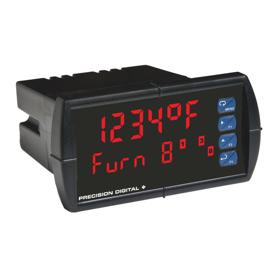
PD7000 Temperature Meter
USB Install
Temperature
www.predig.com
Advertisement
Table of Contents
Troubleshooting

Subscribe to Our Youtube Channel
Related Manuals for Precision Digital Corporation PROVU PD7000


Summary of Contents for Precision Digital Corporation PROVU PD7000
- Page 1 • Input Power Options Include 85-265 VAC or 12-24 VDC • Isolated 24 VDC @ 200 mA Transmitter Power Supply • Modbus® RTU Communication Protocol Standard PRECISION DIGITAL CORPORATION 233 South Street • Hopkinton MA 01748 USA Tel (800) 343-1001 • Fax (508) 655-8990...
- Page 2 Limited Warranty Precision Digital Corporation warrants this product against defects in material or workmanship for the specified period under “Specifications” from the date of shipment from the factory. Precision Digital’s liability under this limited warranty shall not exceed the purchase value, repair, or replacement of the defective unit.
-
Page 3: Table Of Contents
PD7000 Temperature Meter Instruction Manual Table of Contents Table of Contents ----------------------------------------- 3 Relay Action for Loss of Input (Input Break) -------- 25 Relay and Alarm Operation Diagrams ---------------- 26 Table of Figures ------------------------------------------- 4 High Alarm Operation (Set > Reset) ------------------ 26 Introduction ------------------------------------------------- 4 Low Alarm Operation (Set <... -
Page 4: Table Of Figures
PD7000 Temperature Meter Instruction Manual Table of Figures Figure 1. 1/8 DIN Panel Cutout Dimensions ....10 Figure 12. Relay Connections ........13 Figure 2. Panel Mounting Details ....... 10 Figure 13. AC and DC Loads Protection ....14 Figure 3. Meter Dimensions - Side View ....10 Figure 14. -
Page 5: Ordering Information
PD7000 Temperature Meter Instruction Manual Ordering Information Standard Models 85-265 VAC Model 12-24 VDC Model Options Installed PD7000-6R0 PD7000-7R0 No options PD7000-6R2 PD7000-7R2 2 relays (PD1102*) PD7000-6R3 PD7000-7R3 4-20 mA output (PD1103*) PD7000-6R4 PD7000-7R4 4 relays (PD1104*) PD7000-6R5 PD7000-7R5 2 relays & 4-20 mA output (PD1105*) PD7000-6R7 PD7000-7R7 4 relays &... -
Page 6: Temperature Input
PD7000 Temperature Meter Instruction Manual Temperature Three programmable passwords restrict 2C maximum from 0 to 65C ambient Password Drift modification of programmed settings. temperature 4C maximum from -20 to 0C ambient Pass 1: Allows use of function keys and temperature digital inputs Pass 2: Allows use of function keys, digital Offset... -
Page 7: Isolated 4-20 Ma Output
PD7000 Temperature Meter Instruction Manual Modbus ® RTU Serial Communications Relay Reset User selectable via front panel buttons or digital inputs Slave Id 1 – 247 (Meter address) Automatic reset only (non-latching), when the input passes the reset point. Baud Rate 300 –... -
Page 8: Compliance Information
PD7000 Temperature Meter Instruction Manual Compliance Information Safety UL & c-UL Listed USA & Canada UL 508 Industrial Control Equipment UL File Number E160849 Front Panel UL Type 4X, NEMA 4X, IP65; panel gasket provided Low Voltage EN 61010-1:2010 Directive Safety requirements for measurement, control, and laboratory use Electromagnetic Compatibility Emissions... -
Page 9: Safety Information
PD7000 Temperature Meter Instruction Manual Safety Information CAUTION: Read complete WARNING: Risk of instructions prior to electric shock or installation and operation of personal injury. the meter. Hazardous voltages exist within enclosure. Installation and service should be performed only by trained service personnel. -
Page 10: Panel Mounting Instructions
PD7000 Temperature Meter Instruction Manual Panel Mounting Instructions • Prepare a standard 1/8 DIN panel cutout – 3.622" x 1.772" (92 mm x 45 mm). Refer to Figure 1 below, for more details. • Clearance: allow at least 6.0" (152 mm) behind the panel for wiring. Panel thickness: 0.04"... -
Page 11: Connections
PD7000 Temperature Meter Instruction Manual Connections All connections are made to removable screw terminal connectors located at the rear of the meter. Use copper wire with 60°C or 60/75°C insulation for all line voltage connections. Observe all safety regulations. Electrical wiring should be performed in accordance with all applicable national, state, and local codes to prevent Caution! damage to the meter and ensure personnel safety. -
Page 12: Signal Connections
PD7000 Temperature Meter Instruction Manual Signal Connections Signal connections are made to a three-terminal connector labeled SIGNAL on Figure 5. Thermocouple and RTD Connections The following figures show examples for thermocouple and RTD connections. The TYPE selector switch must be set to the proper position for the meter to accept the selected RTD or TC input. -
Page 13: Connections For Averaging Rtd Sensors
PD7000 Temperature Meter Instruction Manual Connections for Averaging RTD Sensors To obtain the average temperature from 2 to 10 RTD sensors, connect all the sensors in parallel and select the number of sensors in the RTD Total (rtdtot) menu. See the Advanced Features Menu on page 34. -
Page 14: Switching Inductive Loads
PD7000 Temperature Meter Instruction Manual Switching Inductive Loads The use of suppressors (snubbers) is strongly recommended when switching inductive loads to prevent disrupting the microprocessor’s operation. The suppressors also prolong the life of the relay contacts. Suppression can be obtained with resistor-capacitor (RC) networks assembled by the user or purchased as complete assemblies. -
Page 15: 4-20 Ma Output Connections
PD7000 Temperature Meter Instruction Manual 4-20 mA Output Connections Connections for the 4-20 mA output are made to the connector terminals labeled MA OUT. The 4-20 mA output may be powered internally or from an external power supply. 24 V 24 V MA OUT MA OUT... -
Page 16: Interlock Relay Feature
PD7000 Temperature Meter Instruction Manual Interlock Relay Feature As the name implies, the interlock relay feature reassigns one, or more, alarm/control relays for use as interlock relay(s). Interlock contact(s) are wired to digital input(s) and trigger the interlock relay. This feature is enabled by configuring the relay, and relative digital input(s) (see page 31). -
Page 17: Setup And Programming
PD7000 Temperature Meter Instruction Manual Setup and Programming The meter is factory calibrated prior to shipment to read temperature in degrees Fahrenheit. The calibration equipment is certified to NIST standards. Overview There are two switches, located at the back of the meter, to set the input selection for TC or RTD and for 100-ohm platinum or 10-ohm copper. -
Page 18: Meterview ® Pro Software
PD7000 Temperature Meter Instruction Manual MeterView ® Pro Software The meter can also be programmed using the PC-based MeterView Pro software included with the meter. This software can be installed on any Microsoft® Windows® (XP/Vista/7/8/10) computer by connecting the meter’s onboard USB. The meter is powered by the USB connection, so there is no need to wire any- thing prior to programming the meter, though USB is intended only for meter configuration. -
Page 19: Display Functions & Messages
PD7000 Temperature Meter Instruction Manual Display Functions & Messages The meter displays various functions and messages during setup, programming, and operation. The following table shows the main menu functions and messages in the order they appear in the menu. Display Parameter Action/Setting Display... - Page 20 PD7000 Temperature Meter Instruction Manual Display Parameter Action/Setting Display Parameter Action/Setting Description Description Relay goes to alarm Enter Control menu Control Contrl condition when input Press Enter to set Automatic Auto break is detected meter for auto Relay goes to non- operation alarm condition when Press Enter to...
-
Page 21: Main Menu
PD7000 Temperature Meter Instruction Manual Main Menu The main menu consists of the most commonly used functions: Setup, Reset, Control, and Password. • Press Menu button to enter Programming Mode then press the Up arrow button to scroll main menu. Press Menu, at any time, to exit and •... -
Page 22: Setting Up The Meter (Setup)
PD7000 Temperature Meter Instruction Manual Setting Up the Meter (setup) It is very important to read the following information, before proceeding to program the meter: • The meter is factory calibrated prior to shipment to read temperature in degrees Fahrenheit. The calibration equipment is certified to NIST standards. -
Page 23: Setting The Input Signal (Input)
PD7000 Temperature Meter Instruction Manual Setting the Input Signal (Input) Enter the Input menu to set up the meter to accept thermocouple (tc) or RTD (rtd) inputs. The Type selector switch, located at the rear of the meter, must be set accordingly. The thermocouple input is capable of accepting various types of thermocouples. -
Page 24: Setting The Input Units Or Custom Tags (Units)
PD7000 Temperature Meter Instruction Manual Setting the Input Units or Custom Tags (units) Enter the input unit or custom tag that will be displayed if alternating rate, total, or grand total and units is selected in the units menu, or d unit is selected as the Lower display parameter. See the flow chart on page 23 to access the display menu to show the unit or tag on the Lower display. -
Page 25: Setting The Relay Action
PD7000 Temperature Meter Instruction Manual Setting the Relay Action Operation of the relays is programmed in the Action menu. The relays may be set up for any of the following modes of operation: 1. Automatic reset (non-latching) 2. Automatic + manual reset at any time (non-latching) 3. -
Page 26: Relay And Alarm Operation Diagrams
PD7000 Temperature Meter Instruction Manual Relay and Alarm Operation Diagrams The following graphs illustrate the operation of the relays, status LEDs, and ACK button. High Alarm Operation (Set > Reset) Low Alarm Operation (Set < Reset) For Manual reset mode, ACK can be pressed anytime For Manual reset mode, ACK can be pressed anytime to turn "off"... -
Page 27: Pump Alternation Control Operation
PD7000 Temperature Meter Instruction Manual Pump Alternation Control Operation Relay Sampling Operation Input Reset Sample Sample Sample Time Time Time Relay When the signal crosses the set point, the relay trips and the sample time starts. After the sample time has elapsed, the relay resets. -
Page 28: Signal Loss Or Input Break Relay Operation
PD7000 Temperature Meter Instruction Manual Signal Loss or Input Break Relay Operation The following graph shows the input break relay operation for a high alarm relay. Input INPUT BREAK INPUT BREAK Reset de-energized energized Relay Input Break = Ignore Relay Input Break = Off Relay Input Break = On... -
Page 29: Relay Operation Details
PD7000 Temperature Meter Instruction Manual Relay Operation Details Overview The relay capabilities of the meter expand its usefulness beyond simple indication to provide users with alarm and control functions. These capabilities include front panel alarm status LEDs as well as either 2 or 4 optional internal relays and/or 4 external relays expansion module. -
Page 30: Latching And Non-Latching Relay Operation
PD7000 Temperature Meter Instruction Manual Latching and Non-Latching Relay Operation The relays can be set up for latching (manual reset) or Relay terminology for following tables non-latching (automatic reset) operation. Terminology Relay Condition Alarm (Tripped) The On and Off terminology does not refer to the status of Normal (Reset) the relay’s coil, which depends on the fail-safe mode Acknowledged... -
Page 31: Acknowledging Relays
PD7000 Temperature Meter Instruction Manual Acknowledging Relays There are two ways to acknowledge relays programmed for manual reset: Via the programmable front panel function keys F1-F3 (Default: F3 assigned to ACK). Remotely via a normally open pushbutton wired across one of the digital inputs and the +5 V terminals on the digital I/O modules, or using the F4 digital input, which is triggered with a contact closure to COM, or with an active low signal (see page 14). -
Page 32: Scaling The 4-20 Ma Analog Output (Aout)
PD7000 Temperature Meter Instruction Manual Scaling the 4-20 mA Analog Output (Aout) The 4-20 mA analog output can be scaled to provide a 4-20 mA signal for any display range selected. No equipment is needed to scale the analog output; simply program the display values to the corresponding mA output signal. -
Page 33: Setting Up The Password (Pass)
PD7000 Temperature Meter Instruction Manual Setting Up the Password (pass) The Password menu is used for programming three levels of security to prevent unauthorized changes to the programmed parameter settings. Pass 1: Allows use of function keys and digital inputs Pass 2: Allows use of function keys, digital inputs and editing set/reset points Pass 3: Restricts all programming, function keys, and digital inputs. -
Page 34: Advanced Features Menu
PD7000 Temperature Meter Instruction Manual Advanced Features Menu To simplify the setup process, functions not needed for most applications are located in the Advanced Features menu. Press and hold the Menu button for three seconds to access the advanced features of the meter. Advanced Features Menu &... -
Page 35: Offset Adjust (Adjust)
PD7000 Temperature Meter Instruction Manual Display Parameter Action/Setting Display Parameter Action/Setting Set byte-to-byte Assign F1 function Time byte F1 function t-byt timeout Enter the Select Assign F2 function Select F2 function SelEct menu Analog Program analog F3 function Assign F3 function AoutPr output output parameters... -
Page 36: Recalibration Of The Meter (T Cal)
PD7000 Temperature Meter Instruction Manual Recalibration of the Meter (t CAL) The Calibration (t CAL) menu is used to recalibrate the thermocouple and RTD inputs. • The meter is factory calibrated prior to shipment to read temperature in degrees Fahrenheit. The calibration equipment is certified to NIST standards. •... -
Page 37: Noise Filter (Filter)
PD7000 Temperature Meter Instruction Manual Noise Filter (filter) The noise filter is available for unusually noisy signals that cause an unstable process variable display. The noise filter averages the input signal over a certain period. The filter level determines the length of time over which the signal is averaged. -
Page 38: Select Menu (Select)
PD7000 Temperature Meter Instruction Manual Select Menu (SElect) The Select menu is used to program the analog output parameters. There are no other selections for this model. Analog Output Programming (AoutPr) The Analog Output Programming menu is used to program the behavior of the 4-20 mA output. The following parameters and functions are programmed in this menu: 1. -
Page 39: Programmable Function Keys User Menu (User)
PD7000 Temperature Meter Instruction Manual Programmable Function Keys User Menu (user) The User menu allows the user to assign the front panel function keys F1, F2, and F3, the digital input F4 (a digital input located on the signal input connector), and up to eight additional digital inputs to access most of the menus or to activate certain functions immediately (e.g. -
Page 40: Internal Temperature Calibration (Ical)
PD7000 Temperature Meter Instruction Manual Internal Temperature Calibration (ICAL) The meter is factory calibrated prior to shipment to read temperature in degrees Fahrenheit. The calibration equipment is certified to NIST standards. The Internal Calibration (ICAL) is a function used at the factory to calibrate all the thermocouple and RTD ranges. - Page 41 PD7000 Temperature Meter Instruction Manual RTD Input Internal Calibration (ICAL) 1. Set the Type selector switch in the RTD position and the Range switch in the 10 position. Using 3 wires connect a precision calibrator resistance output to the meter. 2.
-
Page 42: Meter Operation
PD7000 Temperature Meter Instruction Manual Meter Operation The meter is capable of accepting a variety of thermocouples and RTDs. The dual-line display can be customized by the user to operate in such a way as to satisfy a specific application. Typically, display line 1 is used for the process variable; while line 2 is used engineering units, custom legend, or set point indication. -
Page 43: Maximum/Minimum Readings
PD7000 Temperature Meter Instruction Manual Maximum/Minimum Readings The max & min readings (peak & valley) reached by the process can be displayed either continuously or momentary: 1. Display briefly by assigning to the F1-F3 function keys or to the digital inputs in the User menu. 2. -
Page 44: Troubleshooting
PD7000 Temperature Meter Instruction Manual Troubleshooting The rugged design and the user-friendly interface of the meter should make it unusual for the installer or operator to refer to this section of the manual. However, due to the many features and functions of the meter, it’s possible that the setup of the meter does not agree with what an operator expects to see. -
Page 45: Factory Defaults & User Settings
PD7000 Temperature Meter Instruction Manual Factory Defaults & User Settings The following table shows the factory setting for most of the programmable parameters on the meter. Parameter Display Default Setting Parameter Display Default Setting Input break relay 2 Ignore Input type Type J TC Input ignore... -
Page 46: Troubleshooting Tips
PD7000 Temperature Meter Instruction Manual Troubleshooting Tips Symptom Check/Action Check power at power connector No display at all Meter is password-protected, enter correct six-digit Not able to change setup or password to unlock programming, Locd is displayed Check: Meter displays error message during 1. -
Page 47: Eu Declaration Of Conformity
EN 55022:2010, EN 61000-6-2:2005, EN 61010-1:2010, and EN 61326:2013 and there were no major technical changes affecting the latest technical knowledge for the products listed above. Product Markings: Signed for and on behalf of Precision Digital Corporation: Name: Jeffrey Peters Company:... - Page 48 Call: (800) 343-1001 or (508) 655-7300 Fax: (508) 655-8990 Email: sales@predig.com • For the latest version of this manual, please visit www.predig.com PRECISION DIGITAL CORPORATION 233 South Street • Hopkinton MA 01748 USA Tel (800) 343-1001 • Fax (508) 655-8990 www.predig.com LIM7000_H SFT063 Ver 4.000 &...
Need help?
Do you have a question about the PROVU PD7000 and is the answer not in the manual?
Questions and answers