Table of Contents
Advertisement
Quick Links
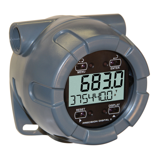
PULSE INPUT RATE/TOTALIZER
Pulse, Open Collector, NPN, PNP, TTL, Switch Contact, Sine Wave
(Coil), Square Wave, Opto-Isolated Inputs
Plastic NEMA 4X, IP65 Enclosure
Isolated 4-20 mA Output for Rate, Total, or Grand Total
5-Digit 0.7" (17.8 mm)Top Display for Rate or Total
7 Alphanumeric Character 0.4" (10.2 mm) Bottom Display for Rate,
Total, Grand Total, Units, and Tag
13-Digit Totalizer with Total Overflow Feature
SafeTouch
®
Battery, DC, or Output Loop-Powered Models
Two Isolated Open Collector Pulse Outputs, Up to 5 kHz
Automatic Rate, Total, & Grand Total Unit Conversions
Password Protection
Backlight Standard on All Models
Operates from -40 to 75°C
Data Logging Functions and Modbus
PRECISION DIGITAL CORPORATION
89 October Hill Road • Holliston MA 01746 USA
Tel (800) 343-1001 • Fax (508) 655-8990
PD6730 VANTAGEVIEW
Through-Window Button Programming
®
Accessible Data
www.predig.com
Advertisement
Table of Contents

Subscribe to Our Youtube Channel
Related Manuals for Precision Digital Corporation Vantageview PD6730


Summary of Contents for Precision Digital Corporation Vantageview PD6730
- Page 1 Backlight Standard on All Models Operates from -40 to 75°C ® Data Logging Functions and Modbus Accessible Data PRECISION DIGITAL CORPORATION 89 October Hill Road • Holliston MA 01746 USA Tel (800) 343-1001 • Fax (508) 655-8990 www.predig.com...
- Page 2 Make sure only qualified personnel perform the installation. Limited Warranty Precision Digital Corporation warrants this product against defects in material or workmanship for the specified period under “Specifications” from the date of shipment from the factory. Precision Digital’s liability under this limited warranty shall not exceed the purchase value, repair, or replacement of the defective unit.
-
Page 3: Introduction
PD6730 Pulse Input Rate/Totalizer Instruction Manual INTRODUCTION The Vantageview PD6730 is a plastic field mounted rate/totalizer designed for rugged and demanding applications in harsh environments. It can be programmed ® using the four SafeTouch through-window buttons, without removing the cover, or with four internal push-buttons. -
Page 4: Table Of Contents
PD6730 Pulse Input Rate/Totalizer Instruction Manual Table of Contents INTRODUCTION --------------------------------------------------------------------------- 3 ORDERING INFORMATION ------------------------------------------------------------ 3 SPECIFICATIONS ------------------------------------------------------------------------- 7 General ------------------------------------------------------------------------------------------------ 7 Rate Input --------------------------------------------------------------------------------------------- 9 Rate/Totalizer --------------------------------------------------------------------------------------- 11 4-20 mA Transmitter Output ------------------------------------------------------------------ 13 ... - Page 5 PD6730 Pulse Input Rate/Totalizer Instruction Manual Custom Units Entry (USER) --------------------------------------------------------------- 45 Custom Units Rate Conversion Factor (ratCF) ------------------------------------ 45 Custom Units Total Conversion Factor (totCF) ------------------------------------ 46 Custom Units Grand Total Conversion Factor (GrtCF)--------------------------- 46 ...
- Page 6 PD6730 Pulse Input Rate/Totalizer Instruction Manual Grand Total Reading (GrTOTAL) -------------------------------------------------------------- 89 Toggle Lower Display Parameter ------------------------------------------------------------ 89 Resetting the Total (RESET TOTAL?) --------------------------------------------------------- 90 Resetting the Grand Total (RESET GrTOT?) ----------------------------------------------- 90 Resetting Max/Min Readings (RESET MAXIMUM, MINIMUM) ---------------------------- 90 ...
-
Page 7: Specifications
PD6730 Pulse Input Rate/Totalizer Instruction Manual SPECIFICATIONS Except where noted all specifications apply to operation at +25°C. General Five Digits Top Dis- 0.7" (17.8 mm) high, 7-segment, DISPLAY play (0 to 99999) automatic lead zero blanking. Seven Characters 0.4" (10.2 mm) high, 14-segment, Bottom Display automatic lead zero blanking. - Page 8 PD6730 Pulse Input Rate/Totalizer Instruction Manual 9-30 VDC Powered, 2.2 W max POWER OPTIONS 4-20 mA Output Powered, 30 VDC max Battery Power 9-30 VDC Powered with Battery Backup 4-20 mA Output Powered with Battery Backup 3.6 V Primary Lithium (Li-SOCl ), non-rechargeable BATTERY Model PDABAT36C...
-
Page 9: Rate Input
PD6730 Pulse Input Rate/Totalizer Instruction Manual All program bned settings and total reading are stored in NON-VOLATILE non-volatile memory for a minimum of ten years if power is MEMORY lost. Screw terminals accept 12 to 22 AWG wire CONNECTIONS NEMA 4X, IP65 plastic field enclosure. ENCLOSURE Color: grey. - Page 10 PD6730 Pulse Input Rate/Totalizer Instruction Manual ±0.03% of calibrated span ±1 count ACCURACY Rate display is not affected by changes in temperature. TEMPERATURE DRIFT LOW-FLOW CUTOFF 0-99,999 (0 disables cutoff function) Up to four decimal places or none: DECIMAL POINT 4.
-
Page 11: Rate/Totalizer
PD6730 Pulse Input Rate/Totalizer Instruction Manual Rate/Totalizer The Top display is assigned to rate or total. The Bottom DISPLAY ASSIGNMENT display is programmable to display total; total and units; total and tag; total, total units, and rate units; grand total; grand total and grand total units;... - Page 12 PD6730 Pulse Input Rate/Totalizer Instruction Manual The total can display up to 9,999,999,999,999. Up to TOTAL 9,999,999 can be displayed on the lower display normally. An OVERFLOW AND overflow display will toggle between the first six digits and last ROLLOVER seven digits (999999 <>...
-
Page 13: 4-20 Ma Transmitter Output
PD6730 Pulse Input Rate/Totalizer Instruction Manual 4-20 mA Transmitter Output OUTPUT SOURCE Rate/process, total, grand total, or disabled 4.000 to 20.000 mA for any display range. SCALING RANGE If disabled, the output will output 3.2 mA DISABLE Factory Calibrated: 0.0 to 1000.0 = 4-20 mA output CALIBRATION Output Underrange: 3.8 mA UNDERRANGE... -
Page 14: Serial Communications
PD6730 Pulse Input Rate/Totalizer Instruction Manual K-factor (couNT) programmable from 0.000001 to 9999999. PULSE OUTPUT Rate pulses are generated as a scaled output of the rate input K-FACTOR with one output pulse per K-factor (count) number of input (COUNT) pulses. Total and grand total pulses are generated for every total or grand total increment selected. -
Page 15: Safety Information
PD6730 Pulse Input Rate/Totalizer Instruction Manual SAFETY INFORMATION WARNINGS Read complete instructions prior to installation and operation of the meter. Installation and service should be performed only by trained service personnel. Service requiring replacement of internal components (not including battery, if equipped) must be performed at the factory. -
Page 16: Installation
PD6730 Pulse Input Rate/Totalizer Instruction Manual INSTALLATION Hazardous voltages may exist within enclosure. Installation and service should be performed only by trained service personnel. WARNING Wiring connectors are accessed by opening the enclosure. To access electrical connectors, remove the 2 captive screws, then disconnect the ribbon cable from the display module and set the display module aside. -
Page 17: Mounting
PD6730 Pulse Input Rate/Totalizer Instruction Manual Mounting The PD6730 has two slotted mounting flanges that may be used for pipe mounting or wall mounting. Alternatively, the unit may be supported by the conduit using the conduit holes provided. Refer to Mounting Dimensions, page 94 for details. Do not attempt to loosen or remove flange bolts while the meter is in service. -
Page 18: Table Of Figures Figure 1. Connector Board
PD6730 Pulse Input Rate/Totalizer Instruction Manual Connections (continued) Signal input positive terminal connection Signal input negative terminal connection DC power supply input return/negative, reset contact closure common Contact closure reset pull-up to 1.8 VDC DC Power positive terminal connection 4-20 mA transmitter DC power positive terminal connection. 4-20 mA transmitter regulated current output terminal connection Open collector output 1 positive terminal OC1+... -
Page 19: Input Signal Connections
PD6730 Pulse Input Rate/Totalizer Instruction Manual Input Signal Connections Signal connections are made to a barrier terminal mounted in the base of the enclosure. Input level and type are configured using the slide switches on the bottom of the display module as shown in the lower right of the following figures. Power Supply Flowmeter... -
Page 20: Figure 5. Npn Open Collector Input (Npn)
PD6730 Pulse Input Rate/Totalizer Instruction Manual +3.0 V SENSOR 100 kOhm Internal Pullup INPUT LEVEL Figure 5. NPN Open Collector Input (NPN) Power Supply SENSOR 100 kOhm Internal Pull-Down INPUT LEVEL Figure 6. PNP Sensor with External Power (PNP) +3.0 V SWITCH CONTACT 100 kOhm... -
Page 21: Dc Power Connection
PD6730 Pulse Input Rate/Totalizer Instruction Manual DC Power Connection Models configured for DC power are provided with a terminal labeled P+ and are wired as shown in Figure 8. Models configured for battery power may optionally be connected to DC power and the battery will function as backup power when DC is lost. The same power supply may be used to power other circuits including a PNP-type sensor, however to maintain input isolation, a separate power supply must be used to power the isolated 4-20 mA transmitter as shown in Figure 10 and/or to power the Opto-Isolated... -
Page 22: 4-20 Ma Transmitter Output Connections
PD6730 Pulse Input Rate/Totalizer Instruction Manual 4-20 mA Transmitter Output Connections Output connections are made to two terminals labeled LP+ and LP-. Connect to an input device such as a remote display or chart recorder as shown in Figure 10. 4-20 mA Input Power Device... -
Page 23: Open Collector Output Connections
PD6730 Pulse Input Rate/Totalizer Instruction Manual Open Collector Output Connections Open collector output 1 and 2 connections are made to terminals labeled OC1+ and OC1-, and OC2+ and OC2-. Connect the alarm or pulse input device as shown in Figure 13. Figure 13. -
Page 24: Battery Replacement
PD6730 Pulse Input Rate/Totalizer Instruction Manual Battery Replacement Battery-equipped models have a battery charge monitor. When the battery is nearing the end of its capacity the screen will periodically flash the message LO BATTERY and the BAT indicator on the screen will flash. The recommended replacement interval for models using the battery as a primary power source is determined by the power and feature use, as shown on page 8. -
Page 25: Setup And Programming
PD6730 Pulse Input Rate/Totalizer Instruction Manual SETUP AND PROGRAMMING There is no need to recalibrate the meter for frequency in Hz when first received from the factory. The meter is factory calibrated for Hz prior to shipment. The calibration equip- ment is certified to NIST standards. - Page 26 PD6730 Pulse Input Rate/Totalizer Instruction Manual ® SafeTouch Button Tips and Troubleshooting The SafeTouch Buttons are designed to filter normal levels of ambient interference and to protect against false triggering, however it is recommended that the ® SafeTouch Buttons be turned off (slide THRU-GLASS BUTTONS switch to OFF) if there is an infrared interference source in line-of-sight to the display or if the buttons are not needed.
-
Page 27: Buttons And Display
PD6730 Pulse Input Rate/Totalizer Instruction Manual Buttons and Display MENU ENTER RESET DISPLAY Button Description Symbol Status Symbol High Alarm Menu/ SafeTouch® Low Alarm Awake MENU Total Alarm RESET Right Arrow/Reset Settings Lockout Password Enabled SafeTouch Power DISPLAY Save/Disable. Up Arrow/ Flashing: Temporarily Disabled Display Due to Mechanical Button... - Page 28 PD6730 Pulse Input Rate/Totalizer Instruction Manual Menu Button Hold the Menu SafeTouch® button when in power save mode (display will show ) to awaken SafeTouch® buttons. Press the Menu button to enter Programming Mode. Press the Menu button during Programming Mode to return to return to the previous menu selections.
-
Page 29: Setting Numeric Values
PD6730 Pulse Input Rate/Totalizer Instruction Manual Setting Numeric Values The numeric values are set using the Right and Up arrow buttons. Press Right arrow to select next digit and Up arrow to increment digit. The digit being changed blinks. Press the Enter button, at any time, to accept a setting or Menu button to exit without saving changes. -
Page 30: Main Menu
PD6730 Pulse Input Rate/Totalizer Instruction Manual Main Menu The main menu separates the most commonly used functions in the Setup menu, and more complex features in the Advanced Features menu. Press Menu button to enter Programming Mode then press the Up arrow button to scroll through the main menu. -
Page 31: Setup Menu Display Functions & Messages
PD6730 Pulse Input Rate/Totalizer Instruction Manual Setup Menu Display Functions & Messages The meter displays various functions and messages during setup, programming, and operation. The following table shows the main menu functions and messages in the order they appear in the menu. Display Parameter Action/Setting... - Page 32 PD6730 Pulse Input Rate/Totalizer Instruction Manual Display Parameter Action/Setting P/HECtL Set K-factor in pulses per hectoliter Pulses/hectoliter Set K-factor custom unit P/CUST Pulses/custom Set the number of decimal points in the Dec. p T K-factor decimal K-factor point Set the K-factor for custom units FAcTR K-factor value Select standard units or custom unit/tag...
- Page 33 PD6730 Pulse Input Rate/Totalizer Instruction Manual Display Parameter Action/Setting Tot U Select total display units Total units Select the total units multiplier Nmult Total multiplier Select no multiplier x1 (no multiplier) Select x100 multiplier with h unit prefix X100 h x100 (h) Select x1,000 multiplier with k unit prefix X1000 k...
- Page 34 PD6730 Pulse Input Rate/Totalizer Instruction Manual Display Parameter Action/Setting GrTOT+U` ` ` ` ` ` ` ` ` Display grand total and units Grand total & units Display the grand total and custom tag GT+TAG Grand total & tag Display the grand total, grand total units, GT+U+RU Grand total &...
-
Page 35: Setting Up The Meter (Setup)
PD6730 Pulse Input Rate/Totalizer Instruction Manual Setting Up the Meter (SETUP) The Setup menu is used to select: Input type selection (INPuT) K-factor number and units (FActr) Display rate, total, and grand total units (Units) Rate and total decimal point position (dec. p t) Select what will appear on the lower display (DSPLY) Press the Enter button to access any menu or press Up arrow button to scroll through choices. -
Page 36: Selecting Input Type (Input)
PD6730 Pulse Input Rate/Totalizer Instruction Manual Selecting Input Type (Input) Seven input types may be set. See Rate Input specifications on page 9 for electrical specifications of the inputs. The following input types may be selected: Active (activ) External power supply driven pulse inputs NPN (NPN) Internal pull-up resistor on S+ for NPN inputs PNP (PNP) - Page 37 PD6730 Pulse Input Rate/Totalizer Instruction Manual...
-
Page 38: Entering The K-Factor (Factr)
PD6730 Pulse Input Rate/Totalizer Instruction Manual Entering the K-Factor (Factr) The meter may be scaled using the K-factor, or conversion factor, function. Most flowmeter manufacturers provide this information with the device. Enter the K-Factor (Factr) menu and select the units defined with the k-factor (example: pulses/gal), the decimal point with highest resolution possible, and program the K-Factor value. -
Page 39: K-Factor Value (Factr)
PD6730 Pulse Input Rate/Totalizer Instruction Manual K-Factor Value (factr) Enter the K-factor value. This value is entered in Pulses/Unit as defined by the K- Factor Units parameter. Most flowmeter manufacturers provide this information with the device. Display Units (Units) The Units menu is used to select the display rate units and time (example: Gal/s) and the display units for total and grand total. - Page 40 PD6730 Pulse Input Rate/Totalizer Instruction Manual The following units may be selected as the base units for rate, total, and grand total. Time base for rate and a multiplier for total and grand total units may also be selected separately. Units Unit Description...
-
Page 41: Setting The Time Base (Tbase)
PD6730 Pulse Input Rate/Totalizer Instruction Manual Setting the Time Base (tbase) The meter calculates rate based on rate time base and rate display units. The time base is the unit of time used to calculate the rate, and can be set as units per second, minute, hour, or day. -
Page 42: Setting The Rate Display Units (Rateu)
PD6730 Pulse Input Rate/Totalizer Instruction Manual Setting the Rate Display Units (rateU) Rate is displayed in terms of a unit of volume, and a time base. The unit selected will be used with the time base to establish the rate unit (example: GAL/S when Units is GAL, and time base is seconds). -
Page 43: Total Units (Tot U)
PD6730 Pulse Input Rate/Totalizer Instruction Manual Total Units (tot U) This menu is used to select the display units for the total. The base unit and a multiplier prefix are selected. If total and units are selected to display, the multiplier prefix will appear before the total unit (example: MGAL, kL). -
Page 44: Grand Total Units (Gtotu)
PD6730 Pulse Input Rate/Totalizer Instruction Manual Grand Total Units (GtotU) This menu is used to select the display units for the grand total. The base unit and a multiplier prefix are selected. If grand total and units are selected to display, the multiplier prefix will appear before the total unit (example: MGAL, kL). -
Page 45: Automatic Unit Conversions
PD6730 Pulse Input Rate/Totalizer Instruction Manual Automatic Unit Conversions When switching from any standard unit of rate, total, or grand total to any other standard unit, automatic unit conversions are performed by the meter. No unit conversions will be performed when the K-Factor Units (FuNiT) menu is set to custom (CUST). -
Page 46: Custom Units Total Conversion Factor (Totcf)
PD6730 Pulse Input Rate/Totalizer Instruction Manual Rate Conversion Factor is used to convert to a custom unit of rate display. For example, to display rate as quantity of 2.5 gallon containers when the K-Factor units are set to gallons, enter a conversion factor of 2. 5 00. Press the Enter button, at any time, to accept a setting or Menu button to exit without saving changes. -
Page 47: Setting The Decimal Point (Dec. P T)
PD6730 Pulse Input Rate/Totalizer Instruction Manual Setting the Decimal Point (dec. P T) Rate decimal point may be set with up to four decimal places or with no decimal point at all. Total decimal point may be set with up to six decimal places or with no decimal point at all. -
Page 48: Configuring The Display (Dsply)
PD6730 Pulse Input Rate/Totalizer Instruction Manual Configuring the Display (Dsply) The top and bottom displays can be independently programmed to display selected information. Top Display (TOp) The top display can be programmed to display rate or total. When displaying total, the top display will only show the 5 least significant digits, with no overflow display, for a total from 0 to 99999. -
Page 49: Bottom Display (Botm)
PD6730 Pulse Input Rate/Totalizer Instruction Manual Bottom Display (bOtm) The bottom display can be programmed to display the following information. 1. Total 8. Alternating grant total, grand total units, and rate units 2. Alternating total and total units 9. Rate 3. -
Page 50: Custom Tag (Tag)
PD6730 Pulse Input Rate/Totalizer Instruction Manual Custom Tag (TAG) When the bottom display selected includes a custom tag, a User menu will then allow a custom tag to be programmed. Any 7-digit 14-segment label may be entered for a custom tag (examples: RATe, LINE 3, WaTER). -
Page 51: Setting The Toggle Time (Time)
PD6730 Pulse Input Rate/Totalizer Instruction Manual Setting the Toggle Time (TIME) If the bottom display is programmed to toggle (TOGLE), the meter will prompt for a toggle time. In addition, it may require a tag be entered, as shown in the example below. -
Page 52: Advanced Features Menu
PD6730 Pulse Input Rate/Totalizer Instruction Manual Advanced Features Menu To simplify the setup process, functions not needed for most applications are located in the Advanced Features menu. Access the Advanced features menu by pressing Enter at the Advance menu in the Main Menu defined on page 30. The Advanced menu is used to select: Open collector output configuration (OUTPUT) Analog output configuration (A OUT) - Page 53 PD6730 Pulse Input Rate/Totalizer Instruction Manual Advanced menus A OUT displayed only for meters with the analog output option, COMM displayed only for meters with the serial communications option, and STANDBY only for meters with battery or battery backup power. Press the Enter button to access any menu or press Up arrow button to scroll through choices.
-
Page 54: Advanced Features Menu & Display Messages
PD6730 Pulse Input Rate/Totalizer Instruction Manual Advanced Features Menu & Display Messages The following table shows the Advanced features menu functions and messages in the order they appear in the menu. Display Parameter Action/Setting Enter Advanced menu ADVANCE Advanced Setup open collector outputs Out 1 and Out 2 OUTPUT Output Assign function of open collector output 1... - Page 55 PD6730 Pulse Input Rate/Totalizer Instruction Manual Display Parameter Action/Setting Output display 2 value Dsp 2 Display 2 Output 2 value OUt 2 Output 2 Save? Save entered analog parameters Save Turn off the analog output dsabl Disable Enter Gate menu GATE Gate Set Low Gate...
- Page 56 PD6730 Pulse Input Rate/Totalizer Instruction Manual Display Parameter Action/Setting Enter the time of day to reset the total time Total Reset Time hh.mm (Default: 00.00 midnight) Set Clock Message indicates that the clock must be set. CLOCK Go to Advance – System – Set Time GTrST Select the Grand Total Reset method Grand total reset...
- Page 57 PD6730 Pulse Input Rate/Totalizer Instruction Manual Display Parameter Action/Setting Set first daily log time (1-4) LOG 1 Log 1 Disable log number DsAbL Disable INTERVL Set interval log time Interval Begin interval logging STArT Start View data log LOGVIEW Log view View all data log points All log view LOGVIEW...
-
Page 58: Open Collector Outputs (Output)
PD6730 Pulse Input Rate/Totalizer Instruction Manual Open Collector Outputs (OUTPUT) The meter is equipped with two NPN open collector outputs that may be set up for pulse outputs, alarms, timed pulses, or turned off. Pulse outputs are based on K-factor, total or grand total counts, or one-for-one retransmit for input pulses. - Page 59 PD6730 Pulse Input Rate/Totalizer Instruction Manual Pulse Output (PUlse) Pulse outputs may be assigned to rate, total, grand total, retransmit, quadrature, or test. Rate Pulse Output (rate) A rate based pulse output is a factor of the rate display and count (output K-factor). The rate display is a factor of the input pulses, time base, and the input K-factor.
- Page 60 PD6730 Pulse Input Rate/Totalizer Instruction Manual A total and grand total based pulse output is a factor of the associated total and count (output K-factor). A pulse will be generated for every total accumulation amount equal to the count. If the maximum output frequency would be exceeded, the meter will display the message pUlse OVERRNG alternating on the display.
- Page 61 PD6730 Pulse Input Rate/Totalizer Instruction Manual Alarm Output (alrm) Alarm outputs may be assigned to rate, total, or grand total; or be forced on or off. Rate Alarm (rate) Program the rate set point to trigger the alarm. Rate alarm deadband is determined by the difference between set and reset points.
- Page 62 PD6730 Pulse Input Rate/Totalizer Instruction Manual If automatic total/grand total reset is enabled, the output will generate an alarm for a period of time programmed in ADVANCE T RESET Auto T DELAY. After this time delay, the total/grand total will reset to 0 and the alarm will clear. If Out 1 and Out 2 are set for total or grand total alarm, the auto reset will be triggered on the highest of the two alarm set points.
-
Page 63: Scaling The 4-20 Ma Analog Output (Aout)
PD6730 Pulse Input Rate/Totalizer Instruction Manual Scaling the 4-20 mA Analog Output (Aout) The Analog Output menu is used to program the 4-20 mA output based on display values. The 4-20 mA analog output (if equipped) can be scaled to provide a 4-20 mA signal for any display range selected for either the rate, total, or grand total. -
Page 64: Gate Function (Gate)
PD6730 Pulse Input Rate/Totalizer Instruction Manual Gate Function (GATE) The gate function is used for displaying slow pulse rates. Using the programmable gate, the meter is able to display pulse rates as slow as 1 pulse every 9,999 seconds (0.0001 Hz). The gate function can also be used to obtain a steady display reading with a fluctuating input signal. -
Page 65: Scaling & Calibration (Scalcal)
PD6730 Pulse Input Rate/Totalizer Instruction Manual Scaling & Calibration (SCALCAL) It is very important to read the following information, before proceeding to program the meter: There is no need to recalibrate the meter for frequency in Hz when first received from the factory. -
Page 66: Scaling The Meter (Scale)
PD6730 Pulse Input Rate/Totalizer Instruction Manual Scaling the Meter (SCale) The pulse input can be scaled to display the process variable in engineering units. A signal source is not needed to scale the meter; simply program the inputs and corresponding display values. A programmed scaled input will work with Automatic Unit Conversions as described on page 45. - Page 67 PD6730 Pulse Input Rate/Totalizer Instruction Manual Multi-Point Linearization (nopts) Up to 32 linearization points can be selected under the nopts function. The multi- point linearization can be used to linearize the display for non-linear inputs. Number of Points (nopts) Enter number of linearization points. The default value is 2 points. For linear inputs requiring only 2 scale points, the number of points can be left at 2.
-
Page 68: Calibrating The Meter (Cal)
PD6730 Pulse Input Rate/Totalizer Instruction Manual Calibrating the Meter (CaL) To scale the meter without a signal source refer to Entering the K-Factor (Factr) on page 38 or Scaling the Meter (SCale) on page 66. The pulse input can be calibrated to display the process in engineering units by applying the appropriate input signal and following the calibration procedure. - Page 69 PD6730 Pulse Input Rate/Totalizer Instruction Manual The multi-point linearization feature (nopts) can be used to linearize the display for non-linear signals. For instructions on how to utilize this feature, see Multi-Point Linearization (nopts), page 70. For instructions on how to program numeric values see Setting Numeric Values, page 29.
-
Page 70: Multi-Point Linearization (Nopts)
PD6730 Pulse Input Rate/Totalizer Instruction Manual Error Message (Error) An error message indicates that the calibration or scaling process was not successful. After the error message is displayed, the meter reverts to input 2 during calibration or scaling, allowing the appropriate input signal to be applied or programmed. The error message might be caused by any of the following conditions: Input signal is not connected to the proper terminals or it is connected backwards. -
Page 71: Manual Or Automatic Total Reset Function (T Rst)
PD6730 Pulse Input Rate/Totalizer Instruction Manual Manual or Automatic Total Reset Function (t rST) For manual reset, select T RESET t rst man and then select whether manual reset will be enabled (Enabl) or disabled (dsabl) using the Up arrow key. Press the Enter button to accept. -
Page 72: Manual Or Automatic Grand Total Reset Function (Gtrst)
PD6730 Pulse Input Rate/Totalizer Instruction Manual Manual or Automatic Grand Total Reset Function (GtrST) For manual reset, select T RESET Gtrst man and then select whether manual reset will be enabled (Enabl) or disabled (dsabl) using the Up arrow key. Press the Enter button to accept. -
Page 73: Setting Up Passwords (Passwrd)
PD6730 Pulse Input Rate/Totalizer Instruction Manual Setting Up Passwords (PASSWRD) The Password menu is used to program a five-digit password to prevent unauthorized changes to the programmed parameter settings, to restrict the ability to reset the total and grand total, and to permanently lockout the ability to reset the grand total and any grand total related parameters. -
Page 74: Resetting Total & Grand Total On A Password Protected Meter
PD6730 Pulse Input Rate/Totalizer Instruction Manual Resetting Total & Grand Total on a Password Protected Meter If the meter is password protected for total or grand total reset, the meter will display the message PASS T or PASS GT when an attempt is made to enter the password protected total or grand total Reset menus. - Page 75 PD6730 Pulse Input Rate/Totalizer Instruction Manual To configure the meter for non-resettable grand total mode, enter the non-resettable grand total password below into the Pass GT parameter in the Password menu. The non-resettable grand total permanently locks the following setup menus and parameters from being changed: input selection, K-factor, K-factor units, grand total units, grand total conversion factor, grand total decimal point, scaling, calibration, grand total alarms, pulse input filter, and cutoff.
-
Page 76: Custom (Custom)
PD6730 Pulse Input Rate/Totalizer Instruction Manual Custom (CUSTOM) The Custom menu is used to modify the initial programming menus that appear in the Main Menu when the Menu button is pressed in Run Mode. Changing the default menu setup with the Custom menu feature may change the setup and operation procedures described in this manual. - Page 77 PD6730 Pulse Input Rate/Totalizer Instruction Manual Custom Menu Parameters Display Parameter/Menu Action Set no menu position display NONE None Set to show Input menu INPUT Input Set to show K-Factor menu KFACTOR K-Factor Select standard units or custom unit/tag UNITs Units Set to show Decimal menu DECIMAL...
-
Page 78: System (System)
PD6730 Pulse Input Rate/Totalizer Instruction Manual Set daily data log times LOGTIME Log Time Set interval log times INTERVL Interval Enter Log View menu LOGVIEW Log View Set to show Password menu PASSWRD Password Set to show Setup menu SETUP Setup Set to show Advanced menu ADVANCE... -
Page 79: Set Real Time Clock (Settime)
PD6730 Pulse Input Rate/Totalizer Instruction Manual Set Real Time Clock (SETTIME) The real time clock is used to trigger data log events, and is recorded at every logged data point. The menu displays the date and time. Figure 15. Date Display Example The above display example shows the date to be June 27, at 14 hours, 32 minutes, and 36 seconds. -
Page 80: Data Log Setup (Datalog)
PD6730 Pulse Input Rate/Totalizer Instruction Manual Data Log Setup (DATALOG) The Data Log menu is used to setup and enable the data log functions. The meter may contain up to 1024 records, each containing date, time, rate, total, grand total, and log number. -
Page 81: View Data Log (Logview)
PD6730 Pulse Input Rate/Totalizer Instruction Manual Log Time Setup (LOGTIME) The Log Time menu contains four log points (LOG 1 to LOG 4). Each log time is configured separately. For each daily log time desired, enable a log, and set the log time for the hours and minutes the log is to be recorded. -
Page 82: Backlight (Baklite)
PD6730 Pulse Input Rate/Totalizer Instruction Manual Once the log records are displayed, use the Up and Right arrows to change the log entry being viewed. The Enter key changes the displayed information for the same log. Backlight (BAKLITE) The Backlight menu is used to enable or disable the backlight. This feature is particularly important for the battery-powered models with momentary backlight. -
Page 83: Battery Power Symbol Alert (Bat Sym)
PD6730 Pulse Input Rate/Totalizer Instruction Manual The save feature (SAvE?) saves all current parameter settings into the memory of the backup restore. The backup restore feature is loaded with factory default settings until a new configuration is saved. The load feature (load?) restores all parameters to the programmed values stored in backup restore memory. -
Page 84: Serial Communications (Comm)
PD6730 Pulse Input Rate/Totalizer Instruction Manual Serial Communications (COMM) The Communications menu is used to setup serial communications parameters necessary for communication via Modbus. Modbus communications is performed with the 2-wire RS-485 with Modbus RTU option. When using more than one meter in a multi-drop mode, each meter must be provided with its own unique address. -
Page 85: Standby Mode (Standby)
PD6730 Pulse Input Rate/Totalizer Instruction Manual Standby Mode (STANDBY) Standby mode is available on battery powered and battery backup models only. The Standby menu is used to enter a power-saving standby mode that will turn off the display and activate a low power mode for the through-window buttons. Signal processing operations will continue to run. -
Page 86: Operation
PD6730 Pulse Input Rate/Totalizer Instruction Manual OPERATION Front Panel Buttons Operation Symbol Description Hold the Menu SafeTouch® button when in power save mode (display will show ) to awaken SafeTouch® buttons. Press the Menu button to enter Programming Mode. ... - Page 87 PD6730 Pulse Input Rate/Totalizer Instruction Manual The following SafeTouch button information is reprinted from SafeTouch Button Operation on page 25. SafeTouch Button Operation To actuate a button, press and remove one finger to the window directly over the marked button area. Remove finger to at least 4 inches away from the window in between button activations.
- Page 88 PD6730 Pulse Input Rate/Totalizer Instruction Manual ® SafeTouch Button Tips and Troubleshooting The SafeTouch Buttons are designed to filter normal levels of ambient interference and to protect against false triggering, however it is recommended that the ® SafeTouch Buttons be turned off (slide THRU-GLASS BUTTONS switch to OFF) if there is an infrared interference source in line-of-sight to the display or if the buttons are not needed.
-
Page 89: Grand Total Reading (Grtotal)
PD6730 Pulse Input Rate/Totalizer Instruction Manual Grand Total Reading (GrTOTAL) The grand total is a separate total that is not reset when the total is reset. This allows the complete total to be tracked by the grand total, while individual batch, or daily totals are reset regularly. -
Page 90: Resetting The Total (Reset Total?)
PD6730 Pulse Input Rate/Totalizer Instruction Manual Resetting the Total (RESET TOTAL?) If manual Total Reset is enabled in the Program menu, the total may be reset by pressing the Reset button and using the Enter button to confirm the reset. Additionally if programmed for manual reset, the total may be reset using a normally open pushbutton connected across the terminals RST and COM. -
Page 91: Factory Defaults & User Settings
PD6730 Pulse Input Rate/Totalizer Instruction Manual Factory Defaults & User Settings The following table shows the factory setting for most of the programmable parameters on the meter. Next to the factory setting, the user may record the new setting for the particular application. Model: ______________ S/N: _______________ Date: _________ Parameter... - Page 92 PD6730 Pulse Input Rate/Totalizer Instruction Manual Parameter Display Default Setting User Setting Scale Enable No – Use K-Factor SCALE Scale/Cal # Points 2 (N/A) nopts Scale Unit Pulses/Gallon (N/A) Funit Second (N/A) Scale Unit Time Base tinme Scale/Cal Input 1 00000 (N/A) Inpt1 Scale/Cal Display 1...
-
Page 93: Troubleshooting
PD6730 Pulse Input Rate/Totalizer Instruction Manual TROUBLESHOOTING The rugged design and the user-friendly interface of the meter should make it unusual for the installer or operator to refer to this section of the manual. If the meter is not working as expected, refer to the recommendations below. Troubleshooting Tips Symptom Check/Action... -
Page 94: Mounting Dimensions
PD6730 Pulse Input Rate/Totalizer Instruction Manual MOUNTING DIMENSIONS All units: inches [mm] 3.35 85.1 2.25 57.2 0.33 8.3 5.67 144.0 5.25 133.3 Figure 16. Enclosure Dimensions – Front View Ø 3.34 84.9 4.18 106.1 Figure 17. Enclosure Dimensions – Side Cross Section View Note: The supplied conduit plug may extend up to 0.21 in [5.3 mm] from the conduit opening when installed. -
Page 95: Quick User Interface Reference
PD6730 Pulse Input Rate/Totalizer Instruction Manual QUICK USER INTERFACE REFERENCE Pushbutton Function Go to Programming mode, back out one level of programming. Menu Hold to enter Advanced Features mode. Leave grand to- tal/max/min mode. Move to next digit or decimal point position. Go to reset menu Right Arrow Return to last programming menu. - Page 96 PD6730 Pulse Input Rate/Totalizer Instruction Manual How to Contact Precision Digital For Technical Support: Call: (800) 610-5239 or (508) 655-7300 Fax: (508) 655-8990 Email: support@predig.com For Sales Support: Call: (800) 343-1001 or (508) 655-7300 Fax: (508) 655-8990 Email: sales@predig.com ...
Need help?
Do you have a question about the Vantageview PD6730 and is the answer not in the manual?
Questions and answers