CAME BXL04AGS Installation Manual
Sliding-gate operators
Hide thumbs
Also See for BXL04AGS:
- Installation, operation and maintenance manual (25 pages) ,
- Installation, operation and maintenance manual (96 pages)

Related Manuals for CAME BXL04AGS


Summary of Contents for CAME BXL04AGS
- Page 1 FA01947-EN Sliding-gate operators BXL04AGS BXL04ALS INSTALLATION MANUAL Italiano...
- Page 3 • The manufacture date is provided in the production batch printed on the product label. If necessary, contact us at https://www.came.com/global/en/contact-us. • The general conditions of sale are given in the official CAME price lists.
-
Page 4: Dismantling And Disposal
DISMANTLING AND DISPOSAL CAME S.p.A. employs an Environmental Management System at its premises. This system is certified and compliant with the UNI EN ISO 14001 standard to ensure that the environment is respected and safeguarded. Please continue safeguarding the environment. At CAME we consider it one of the fundamentals of our operating and market strategies. -
Page 5: Intended Use
801MS-0140 BXL04AGS - Operator with 24 V motor, featuring a control board with DIP switch settings, on-board radio decoding, movement and obstruction detecting device for sliding gates weighing up to 400 kg that are up to 10 m long. RAL7024 grey cover. -
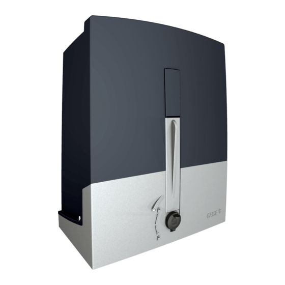
Page 6: Description Of Parts
Description of parts Operator Cover Control board holder Board-holder support Release lever Gearmotor Lock Anchoring plate Mechanical limit-switch tabs Screws UNI5739 12X60 EMC02 control board Washer Ø 12 Transformer Nut UNI5588 M12 Mechanical limit switch Board protection cover Release key Control board... -
Page 7: Control Board
Control board Before working on the control panel, disconnect the mains power supply and remove the batteries, if any. Use DIP switches to set functions and the trimmer for adjustments. All connections are protected by quick fuses. For the system to work properly, before fitting any plug-in card, DISCONNECT THE MAIN POWER SUPPLY and remove any batteries. DIP switches Terminal board for powering accessories Trimmer... - Page 8 Size Usage limitations MODELS BXL04AGS BXL04ALS Maximum gate-leaf length (m) Maximum gate-leaf weight (kg) Fuse table MODELS BXL04AGS BXL04ALS Line fuse 1.6 A-F Accessory fuse 2 A-F Technical data MODELS BXL04AGS BXL04ALS Power supply (V - 50/60 Hz) 230 AC...
- Page 9 Cable types and minimum thicknesses Cable length (m) up to 20 from 20 to 30 Power supply 230 V AC 3G x 1.5 mm2 3G x 2.5 mm2 24 V AC/DC flashing beacon 2 x 0.5 mm2 2 x 0.5 mm2 TX Photocells 2 x 0.5 mm2 2 x 0.5 mm2...
-
Page 10: Installation
INSTALLATION The following illustrations are examples only. The space available for fitting the operator and accessories varies depending on the area where it is installed. It is up to the installer to find the most suitable solution. The drawings show an operator fitted on the left. Preliminary operations Dig a hole for the foundation frame. - Page 11 Insert the screws supplied in the anchoring plate. Lock the screws in place with the nuts supplied. Remove the pre-shaped clamps using a screwdriver. Fit the anchoring plate in the iron cage. The tubes must pass through the existing holes. UNI 5588 M12 Ø...
- Page 12 Remove the nuts from the screws. Insert the electrical cables into the tubes until they protrude by about 600 mm. Setting up the operator Remove the operator cover. Place the operator on top of the anchoring plate. The electrical cables must pass under the operator foundation frame Make a hole in the cable gland.
- Page 13 Fastening the rack Release the operator. Rest the rack on the pinion. Weld or fasten the rack to the gate along its entire length. To assemble the rack modules, use an extra piece and rest it under the joint, then fasten it in place using two clamps. Adjusting the pinion-rack coupling Open and close the gate manually.
- Page 14 Fastening the operator in place Only fasten the operator after adjusting the pinion-rack coupling. Fasten the operator to the anchoring plate using stoppers and nuts. Determining the travel end points with mechanical limit switches Open the gate. Insert the opening limit-switch tab in the rack. The spring must trigger the microswitch.
- Page 15 Close the gate. Insert the closing limit-switch tab in the rack. The spring must trigger the microswitch. Fasten the closing limit-switch tab using the grub screws supplied.
-
Page 16: Electrical Connections
ELECTRICAL CONNECTIONS Passing the electrical cables Connect all wires and cables in compliance with the law. The electrical cables must not touch any parts that may overheat during use (such as the motor and transformer). Use cable glands to connect the devices to the control panel. One of these must be used exclusively for the power supply cable. Power supply Make sure the mains power supply is disconnected during all installation procedures. -
Page 17: Command And Control Devices
Additional light It increases the light in the manoeuvring area. Flashing beacon It flashes when the operator opens and closes. Command and control devices Component for R800 card Control device (NO contact) OPEN-CLOSE-INVERT function from control device (NO contact). Alternatively, when programming, you can activate the OPEN-STOP-CLOSE-STOP function. -
Page 18: Safety Devices
Safety devices Connect the safety devices to the CX input (NC contact). During programming, configure the type of action that must be performed by the device connected to the input. DELTA photocells DELTA photocells Standard connection Connection with safety test See services test function 11 NO C NC 11 NO C NC... - Page 19 Connecting the gearmotor with encoder and limit switches Opening limit-switch (NC contact) Closing limit-switch (NC contact) Encoder Green cable Brown cable White cable 24 V DC gearmotor...
-
Page 20: Programming Functions
Programming functions DIP switches P1 button Control button Red LED (PRG) Run programming following the function order as shown below. The operator must be stationary during programming. When programming is finished, set all DIP switches to OFF. - Page 21 Opening direction The operator is default configured to open towards the left. To configure opening to the right, select the DIP switches as shown and press P1. The LED will remain on and the buzzer will sound for 1 second. To return to the default configuration, press P1 again.
- Page 22 Encoder The function is enabled by default. To disable it, select the DIP switches as shown and press P1. The LED will flash and the buzzer will sound twice. To return to the default setting, press P1 again. The LED will remain on and the buzzer will sound for 1 second. Hold-to-run The function is disabled by default.
- Page 23 Deleting all users Select the DIP switches as shown, and press and hold P1 for 5 seconds. Once all users have been deleted, the LED will remain on and the buzzer will sound for 1 second. The LED will flash and the buzzer will sound twice. Resetting parameters Select the DIP switches as shown and press P1.
-
Page 24: Final Operations
FINAL OPERATIONS Before closing up the casing, check that the cable inlets are sealed to stop insects getting in and to prevent damp. MCBF Models BXL04AGS BXL04ALS Length - Weight 10 m - 400 kg 10 m - 400 kg...
Need help?
Do you have a question about the BXL04AGS and is the answer not in the manual?
Questions and answers