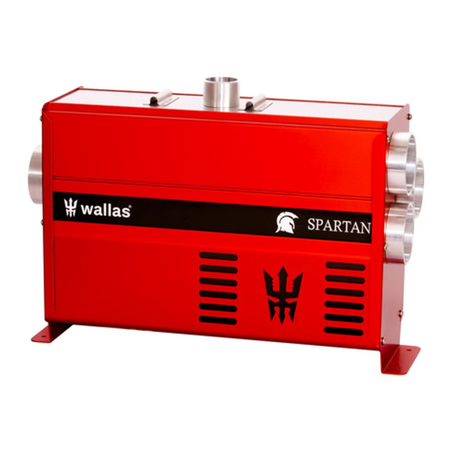
wallas Spartan Technical Information
Hide thumbs
Also See for Spartan:
- Installation, operation and service instructions (109 pages) ,
- Manual (48 pages) ,
- Manual (40 pages)
Table of Contents
Advertisement
Quick Links
Technical information
.....................................................................................................................................................................................
Technical information
.....................................................................................................................................................................................
Technical information
.....................................................................................................................................................................................
Technical information
.....................................................................................................................................................................................
Installation
- Fastening the device
.....................................................................................................................................................................................
Installation
- Electrical connections
.....................................................................................................................................................................................
Installation
- Electrical connections of the device
...................................................................................................................................................................................
Installation
- Warm air ducting
...................................................................................................................................................................................
Exhaust gas connections
...................................................................................................................................................................................
Exhaust gas connections
...................................................................................................................................................................................
Exhaust gas connections
...................................................................................................................................................................................
Exhaust gas connections
...................................................................................................................................................................................
Exhaust gas connections
...................................................................................................................................................................................
Exhaust gas connections
...................................................................................................................................................................................
Fuel connections
- Fuel connections
...................................................................................................................................................................................
Fuel connections
- Fixed tank connection 30011
...................................................................................................................................................................................
Fuel connections
- Installation instructions for separate tank connection
...................................................................................................................................................................................
Installation
- Solenoid valve
...................................................................................................................................................................................
Fuel connections
- Selecting the fuel
...................................................................................................................................................................................
Fuel connections
- Tank external filters
...................................................................................................................................................................................
Control Panel Installation
...................................................................................................................................................................................
Control Panel installation
...................................................................................................................................................................................
Operation panel
- Controlling the device
...................................................................................................................................................................................
Maintenance
- Maintenance recommendations
...................................................................................................................................................................................
Warranty terms
- Warranty terms
...................................................................................................................................................................................
Back cover
- Wallas - Spartan
...................................................................................................................................................................................
- Accessories and measures
- Technical information
- Operation description
- Installation
..............................................................................................................
................................................................................................................
..............................................................................................................
....................................................................................................................
- Exhaust gas connections
- Stern lead-through 5400
- Closable lead-through 2460
- Side lead-through 2467
- Side and deck lead-through 1066, 2466
- Insulation kit
....................................................................................................
...........................................................................................................
.........................................................................................................................
..........................................................................................................
.....................................................................................................
- Steps
................................................................................................................
- Parts
.................................................................................................................
...................................................................................................
...............................................................................................................
......................................................................................................................
....................................................................................
............................................................................................
............................................................................................
....................................................................................
...............................................................................
...............................................................................
..........................................................................
.................................................................................
.....................................................
......................................................................................
........................................................................................
- 1 -
Spartan
..........................................
2
2
3
3
4
4
5
5
6
6
9
9
10
10
13
13
14
14
16
16
17
17
19
19
21
21
23
23
24
24
26
26
27
27
28
28
30
30
31
31
32
32
33
33
34
34
40
40
41
41
42
42
Advertisement
Table of Contents

Subscribe to Our Youtube Channel
Related Manuals for wallas Spartan


Summary of Contents for wallas Spartan
- Page 1 ....................................Control Panel installation - Parts ............................................................ Operation panel - Controlling the device ........................................................Maintenance - Maintenance recommendations ......................................................Warranty terms - Warranty terms ..........................................................Back cover - Wallas - Spartan ............................................................- 1 -...
- Page 2 - 1 -...
- Page 3 Spartan Accessories and measures 2467 Hull lead-through 5400 Stern lead-through, 28 / 45 mm 2448 Exhaust 3410 Warm air duct ø 75 mm 3419 Insulated warm air duct d 75 mm 2460 Sealable deck lead-through 3416 Silencer 30012 Magnetic valve 12V/0,5 A...
-
Page 4: Technical Information
/ importer) Solenoid valve Connections Remote control 2467, 2460, 5400 when coaxial Suitable Exhaust gas lead-throughs 1066, 5400, 2466 when single Due to physical laws of thermodynamics, Wallas-Marin announces measured values with 10 % tolerance. - 3 -... -
Page 5: Operation Description
Operation description The Viking Air / The Spartan Air heater is forced air diesel heater without an exposed flame. Viking and Spartan models take combustion air from outside the boat through the outer coaxial exhaust gas pipe and blow their exhaust out through the inner coaxial pipe. -
Page 6: Installation
If possible, install the control panel on a vertical surface. We recommend that the device be installed by an authorized Wallas service shop or installer. Things to note when installing pipes, hoses and cables Power cables, warm air and fuel hoses must be protected in locations where they are susceptible to mechanical damage due to sharp edges or heat. -
Page 7: Fastening The Device
Spartan Fastening the device Floor mounting the device The heater has "legs" with the two screw holes in each leg. Screw the screws to the solid stable and plane and not over 5 degree angle from horizontal plane. The screws are in the accessory bag. - Page 8 Spartan Lift the heater into the installation plate - 7 -...
- Page 9 Spartan And Lock the device with the mounting bolts. - 8 -...
-
Page 10: Electrical Connections
Spartan Electrical connections Heater has to be connected up electrically according to the EMC-directives. Safety instructions for wiring the heater: Make sure that electrical cables are not damaged. Avoid: chafing, kinking, jamming or exposure to heat. Electrical connections and ground connections must be free of corrosion and firmly connected. - Page 11 Spartan Electrical connections of the device Remote wire 363640 If the heater is needed to be shut down from the boat's main switch, use the spare part 363640 to the heater, and connect the another end of the wire to the main switch. The heat will not start without turning the switch ON, and it will shut down when the switch has been turned OFF.
- Page 12 Spartan Electrical connections of the device 12 V direct current system Connect the red wire of the power cord to the plus terminal of the battery and the black or blue wire to the minus terminal. A 15 A main fuse must be installed near the battery on the red plus wire of the power cord. See picture.
- Page 13 Spartan Note that unit doesn't work without 12V voltage to the "remote" pin, so its necessary to connect enable wire to the main switch, or do a enable jumper instructed in section "24V system" 24 V direct current system If the device is to receive power from a 24 V system, always connect a charging voltage reducer and a 12 V battery before connecting the device.
- Page 14 Spartan Warm air ducting Warm air ducting of the heater It is important to plan the proper routing of the duct and the locations of the air registers. It is good to locate the heater as near as possible to the area being heated. Avoid the use of sharp bends in the ducting and keep overall bends to a minimum.
- Page 15 Exhaust gas connections Exhaust gas lead-throughs Exhaust gas lead-throughs 2467 and the closable model 2460 are suitable for Wallas unit. The ø 28/45 mm lead- throughs fit the exhaust gas hose 2448, providing maximum wind tolerance. Optionally, the Wallas unit can be run using singular exhaust hose 1028 with 1030 insulation sock and the 1066 exhaust lead-through.
- Page 16 Spartan Exhaust gas is hot. Always ensure that there is nothing that is susceptible to heat damage within 200 mm (8") of the effective area of the exhaust gases (e.g. ropes, fenders or the side of another boat). All lead-through's raise the temperature of their surroundings.
- Page 17 Spartan Stern lead-through 5400 Exhaust lead through for negative transom. Designed especially for sail boat´s stern. - 16 -...
- Page 18 Spartan Closable lead-through 2460 The cap of the closable lead-through must be detached for installation and seal maintenance by pressing the spring indicated by the arrow in with, for instance, a screwdriver. Take care not to let the screwdriver slip as the spring is very stiff.
- Page 19 Spartan 1 pcs Accessory bag 17676 4 pcs Fastening screw M5 x 85 mm 8 pcs Nut M5 4 pcs Washer 5,3 x 15 mm 4 pcs Washer 5,3 x 10 mm 1 pcs Hose binder 32 - 50 mm...
- Page 20 Spartan Side lead-through 2467 A side lead-through is installed in the side of the boat or in the transom. In sailboats it is recommended to install it in the transom. The installation always requires a so-called goose neck piece. Make the necessary installation cut-outs and spread a suitable sealing agent on both sides of the seal and on the screw holes.
- Page 21 Spartan 1 pcs Accessory bag 17679 4 pcs Fastening screw M5 x 40 mm 4 pcs Nut M5 4 pcs Washer 5,3 x 10 mm 1 pcs Hose clamp 32 - 50 mm 1 pcs Gasket - 20 -...
- Page 22 Spartan Side and deck lead-through 1066, 2466 Installallation of the exhaust gas connections In single exhaust gas hose installations ø 28 mm (1028). The coaxial hose is not needed. 1. Side installation (1066). 2. Deck installation (2466). - 21 -...
- Page 23 Spartan The exhaust gas tube reaches a high temperature! Be sure that the tube does not touch flammable materials and double check the connections. Insulation sock 1030 is available as an accessory. 2. 2466 deck lead-through installation with singular exhaust hose.
- Page 24 Spartan Insulation kit Insulation kit for a metal-hulled boat An insulation kit must be used to insulate the lead-through from the boats metal hull. The insulation kit insulates the exhaust gas lead-through and the device from each other. In fault situations the electric circuit runs between the metal hull and the device.
-
Page 25: Fuel Connections
The standard length of the fuel hose is 4 m (max 8 m). Cut the fuel hose to a length suitable for installation. The lift height of the pump should be less than 2 m; preferably 0.5-1 m. The fuel pipe must always have a Wallas filter. The fuel filter can be installed either near the device, near the tank, or in another location where it can be easily checked and replaced, when necessary. - Page 26 Spartan Cap run-throughs and sintered filters are used on plastic tanks. The fuel tank should be mounted securely. Wallas fuel tanks Volume Lenght x height x width Order code 200 x 300 x 130 mm 2024 (accessory) 380 x 195 x 210 mm...
- Page 27 Spartan Fixed tank connection 30011 Installation instructions for Tank connection 30011 You will need to make a Ø 25 mm (1") hole in the upper surface of the fuel tank. Choose the location of the hole so that when the fuel tank tilts the end of the intake pipe will stay in the fuel even if the tank is not full. If the end of the intake pipe does not reach the fuel, the device will quickly choke on the air in the fuel system.
- Page 28 If the fuel will be taken from a separate Wallas day tank, you must install a tank connection 367215 (4 m) / 367216 (6 Tighten the barrel nut tightly to the fuel pump connector at the device end of the fuel system. Keep the parts and the hose clean and ensure that the connection is tight, because an air leak in the connector will stop the device from functioning.
-
Page 29: Solenoid Valve
Spartan Solenoid valve - 28 -... - Page 30 Spartan The solenoid valve 30012 prevents the tank from emptying in case the fuel line breaks. The fuel filter should be installed before the solenoid valve. Our recommendations in the following installation scenarios: 1. Fuel level is below the heater/stove. Picture 1.
-
Page 31: Selecting The Fuel
Spartan Selecting the fuel When selecting the fuel type, take note of the temperature limits of each particular fuel. The limit values provided here are to be treated as guidelines. Confirm the actual temperature limits from the fuel supplier. HVO-Diesel, Diesel, summer grade, temperature must not fall below -5 °C. - Page 32 Spartan Tank external filters Filters can be installed in a ø 5 or ø 6 mm plastic tubing or 1/8" metal pipe. Ensure that the fuel pipes are clean before installing the filter. There must be no debris or impurities between the pump and the filter as they will clog the pump.
- Page 33 Spartan Steps - 32 -...
- Page 34 Spartan Parts - 33 -...
-
Page 35: Controlling The Device
Spartan Controlling the device Operation panel is controlled with rotary switch and selection button. Rotary switch can be used turning frame right or left. Button is integrated to panel and is used by pressing upper face of panel. First time start up When connecting power first time, the panel opens a tutorial for operations. - Page 36 Spartan When burner ignites, the flame indicator light is turned on. - 35 -...
- Page 37 Spartan When starting protocol is completed mode indicator "starting" turns off. Selected function is highlighted. When something needs adjustment, select wanted function by turning rotary switch, push button and do wanted changes by rotary switch. Accept changes pushing the button.
- Page 38 Spartan Turning on the additional water pump. This function controls the relay left on the units circuit board, and is designed to be used for additional water pump for circulating water through heated seats, mats or other possible water circulations.
- Page 39 Spartan Manual control On manual control the heating power can be adjusted between 1-6. Heater is turned off by selecting power indicator and long press of button. - 38 -...
- Page 40 Spartan - 39 -...
-
Page 41: Maintenance Recommendations
Spartan Maintenance recommendations Special recommendations Occasional (monthly) use of the device will increase reliability by purging old fuel. If the device uses the same tank as the engine: Observe the engine manufacturers recommendation with regard to the fuel type and moisture removal. -
Page 42: Warranty Terms
1. In the event of a defect: Look at the check list on the website or installation / usage manual (www.wallas.fi) to make sure the defect in question is not related to use. A simple problem might not be covered by the warranty water in diesel or unit requires a service. - Page 43 Spartan Wallas - Spartan Wallas-Marin Oy Kärrykatu 4 20780 Kaarina Finland http://www.wallas.com/ Oikeudet muutoksiin pidätetään. Vi behåller rätten att göra ändringar. We reserve the right to changes. Änderungen vorbehalten. Nous nous réservons le droit de faire des changements. Wij behouden ons het recht voor deze te wijzigen.
Need help?
Do you have a question about the Spartan and is the answer not in the manual?
Questions and answers