Table of Contents
Advertisement
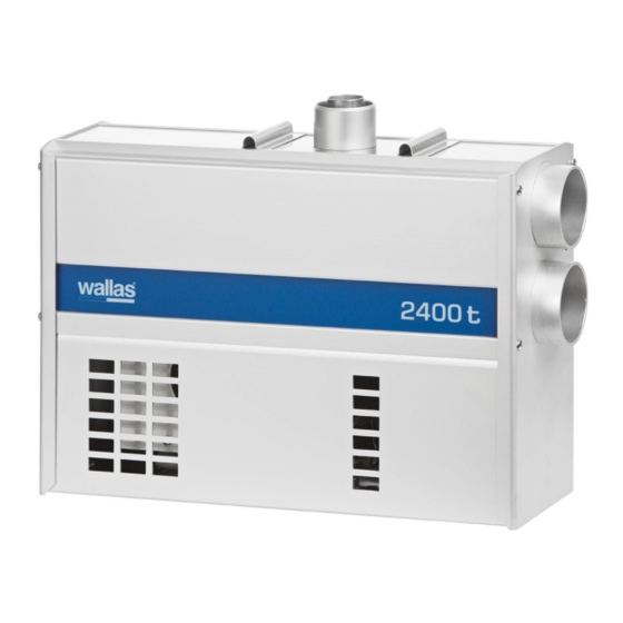
1800 t / 2400 t
2460
2069
2411
3415
Package contents
1800 t / 2400 t
1 pcs
Heater (fuel hose and control panel cable installed)
1 pcs
1
Mounting plate
1 pcs
Accessory bag 17662B
2 pcs
2
2 pcs
3
6 pcs
4
1 pcs
5
2 pcs
6
1 pcs
7
1 pcs
8
2 pcs
9
1 pcs
Control panel package 361066
1 pcs
10
1 pcs
11
4 pcs
12
4 pcs
13
1 pcs
Installation, operation and maintenance instructions
2448
MAX 2m
28/45mm
2412
60
2410
1800,
MAX 5m
2400,
MAX 8m
2413
6m
12V
1800 2400
6,2
7
kg
kg
Mounting bolt M8 x 120 mm DIN 931 / ISO 4014
Corrugated base plate M8 DIN 137 A
Fastening screw 4,8 x 16 mm DIN 7981 / ISO 7049
Hose binder 32 - 50 mm
Hose binder 50 - 70 mm
Fuse box
Fuse 15 A (blue)
Push on contact 6.3 x 0.8 (yellow)
Control panel
Extension collar
Control panel fastening screws 3,5 x 20 mm (black) TX10
Control panel fastening screws 3,5 x 40 mm (black) TX10
- 67 -
en
en
2467
1,55m
10L
5L
490535
Advertisement
Table of Contents


Need help?
Do you have a question about the 2400 t and is the answer not in the manual?
Questions and answers