Advertisement
Table of Contents
- 1 Technical Information
- 2 Heater Operation
- 3 Installation
- 4 Safety Distances
- 5 Electrical Connections
- 6 Checking the Connection
- 7 Fuel Connections
- 8 Country-Specific Requirements
- 9 Operation
- 10 Remote Control
- 11 First Start-Up
- 12 Cleaning and Maintaining the Device
- 13 Maintenance Recommendations
- 14 Special Recommendations
- Download this manual
D80151
26CC / 40CC
Technical information
4031
Standard delivery Installation accessory Special installation
Supplies and accessories
4031
Fuel tank socket case
Timer/week program, mechanical
4206
363055
Timer cable
4430
Remote control system
4004
Exhaust head
4880
Mounting kit
30017
Solenoid valve
4130
Fuel tank, 130 l
4030
Fuel tank, 30 l
2027
Fuel tank, 10 l
4045
Combustion air pipe Ø 45 mm, Al
4845
Exhaust pipe Ø 50/45 mm, stainless
4033
Protection tube 0,5 m, fuel hose
363054
Control panel cable, 6 m
4032
Extension line, 2 m
4012
Insulating channel
4015
Insulation mantel plate Ø 115 mm / 0,3 m
4004
4206
4032
30017
4033
- 37 -
en
4845
4045
4880
604
398
.ai
1 3.1
1.2 011
13: 38:
19
4430
4212
Accessory
26CC / 40 CC
490525C
Advertisement
Table of Contents

Related Manuals for wallas 26CC


Summary of Contents for wallas 26CC
- Page 1 13: 38: 4032 4430 4212 30017 4031 4033 Standard delivery Installation accessory Special installation Accessory Supplies and accessories 26CC / 40 CC 4031 Fuel tank socket case Timer/week program, mechanical 4206 363055 Timer cable 4430 Remote control system 4004 Exhaust head...
-
Page 2: Technical Information
Alternative front panels and their content 26GF 1 pcs Front panel, grey 26CC 4 pcs Fastening screw M4x16 26PF 1 pcs Front panel, pine pattern 26CC 4 pcs Fastening screw M4x16 40GF 1 pcs Front panel, grey 40CC 4 pcs Fastening screw M4x16... -
Page 3: Heater Operation
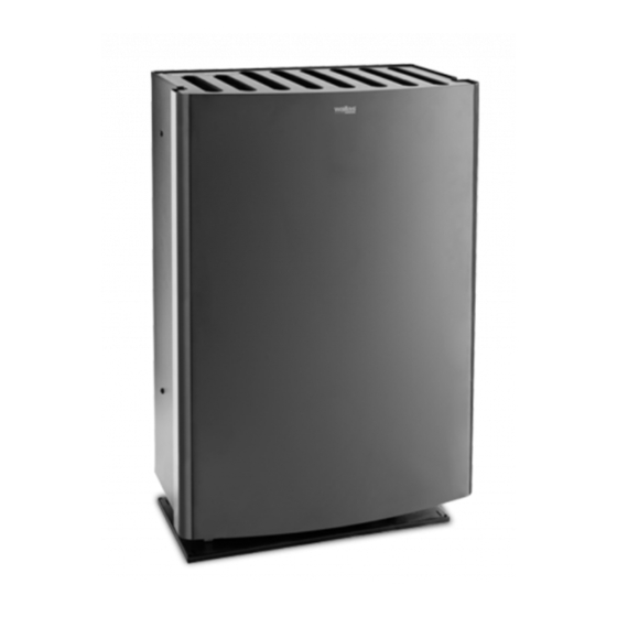
26CC / 40CC Technical information Heater operation Wallas heaters 26CC and 40CC have been designed especially for use in holiday cottages. Light furnace oil, diesel oil or paraffin can be used to fuel the device. The heater is fed with fuel from a separate tank, which is positioned below the heater. The heater is powered by a 12-volt battery, which can be recharged, for example, by a solar cell, wind generator or a mains power adapter. - Page 4 26CC / 40CC Technical information Operating principles 12 V D80151 490525C - 40 -...
-
Page 5: Installation
Avoid installing the control panel in the immediate vicinity of a water outlet. If possible, install the control panel on a vertical surface. We recommend that the device be installed by an authorised Wallas service shop. D80151 490525C... -
Page 6: Safety Distances
The connector is in the accessory bag. Do not remove the jumper (or change its location) from the device’s circuit board. Short circuit connector for mountain switch Always use original Wallas accessories and parts with Wallas equip- ment. D80151 490525C... - Page 7 & date Product must fulfil the RoHS-directive (Directive 2002/95/EY) requirements. and Norway). Note the different measurements for models 26CC and 40CC. • the combustion air intake pipe (ø 50 mm). The cover plate (16) can be used as a stencil. 11. Cut both pipes (18 and 21), so that the pipes extend from the wall ca. 40 - 45...
- Page 8 26CC / 40CC Installation protrudes from the wall ca. 10 mm, and cut the edge of the sheet metal into 10–20 mm strips (28), as shown in . Fold the strips carefully on to the picture 1 surface of the sheet metal cover.
- Page 9 26CC / 40CC Installation 100 mm (sv)(no) 70 mm Picture 1. ø 320 mm insulation Installation in Finland Installation in Sweden and Norway D80151 490525C - 45 -...
- Page 10 26CC / 40CC Installation Instructions for attachment to the flue Accessory 4880 is required for the installation. 1. Cut the flue-gas pipe, the insulation channel and the cover sheet metal to a length at which they extend to the inner surface of the flue. 2. Fasten the hoses to the heater with clamps. The flue-gas pipe must be tight- ened firmly with a pipe clamp. 3. Put the heater in place, and fasten it to the floor or the base housing. 4. Insulate the joint between the flue-gas hose and flue with acrylic compound. 5. The device is ready for use after you connect the power cord and the fuel hose. Note! If you choose to lead in the combustion air from under the floor, ensure there is suf- ficient ventilation in the foundations beneath the floor. Install the protective spiral on...
-
Page 11: Electrical Connections
26CC / 40CC Installation Electrical connections Things to note about the connections The device uses 12 V direct current voltage. To minimise current losses, make the power cable as short as possible and avoid jointing. The cross-sectional area of the cable is dependent on the length of the power cord. -
Page 12: Fuel Connections
26CC / 40CC Installation Fuel connections Things to note about the connections The standard length of the fuel hose is 4 m (max 6 m). Cut the fuel hose to a length suitable for installation. The lift height of the pump should be less than 2 m; preferably 0.5–1 m. - Page 13 26CC / 40CC Installation Connection to a separate tank Cap run-throughs and sinter filters are used on plastic tanks. Wallas fuel tanks Volume length x height x width Order code 2024 200 x 300 x 130 mm Accessory 10 l 380 x 195 x 210 mm 2027 Accessory 30 l...
- Page 14 26CC / 40CC Installation Fuel Several different types of fuel can be used in the heater. When selecting the fuel type, take note of the temperature limits of each particular fuel. The limit values provided here are to be treated as guidelines. Confirm the actual temperature limits from the fuel supplier. • light furnace oil / diesel, summer grade, temperature must not fall below –5 °C •...
- Page 15 26CC / 40CC Installation Accessories Fuel tank socket case, 4031 The base housing enables the device to be installed directly on the fuel tank. A 30-litre fuel tank 4030 can be installed inside the housing. The front panel of the housing contains an opening, through which the fuel level can be easily observed.
-
Page 16: Operation
26CC / 40CC Operation Device use Normal use Temperature is controlled by the thermostat (recommended use). The device starts when the power switch (3) is pressed in continuously for at least 2 seconds, after which the yellow current indicator light (4) lights to indicate that the power is on. -
Page 17: Remote Control
26CC / 40CC Operation After the heater has been started up, the power can be adjusted step-less with the power adjustment knob (2). Avoid turning the adjustment knob back and forth rapidly, as this can cause the burner to become sooty. -
Page 18: Maintenance Recommendations
26CC / 40CC Maintenance Maintenance recommendations Basic maintenance of diesel-operated devices Maintenance procedure Maintenance interval Carried out by Performed by the user ac- Inspection of basic functions After the first 100 l, or after the first cording to the maintenance season of use instructions Performed by the user ac-...
Need help?
Do you have a question about the 26CC and is the answer not in the manual?
Questions and answers