Table of Contents
Advertisement
Quick Links
DS1033-145D
RIVELATORE IR CON PET IMMUNITY
IR DETECTOR WITH PET IMMUNITY
Sch./Ref. 1033/013
CARATTERISTICHE TECNICHE
Pet Immunity con selezione della dimensione dell'animale su due livelli
Tensione nominale di alimentazione: ... 12V
Assorbimento a 12 V : ....................... 10mA nom. 17mA max
Copertura totale: .................................. 90° per 12 m
Zone sensibili: ...................................... 18 su 4 piani
Opto Relè di allarme: ............................ 100mA / 24V
Tamper antimanomissione: .................. 100 mA / 30V
Tempo Allarme: .................................... 3 sec
Temperatura di funzionamento: ............ -10°C ÷ +55°C
Umidità Ambientale: ............................. 95%
MTBF Teorico: ..................................... 120.000 ORE
Dimensioni (h x l x p): ........................... 75 x 60 x 45 mm
Peso: .................................................... 65 g
Livello prestazione:............................... EN50131-2-2 Classe II, Grado 2
ACCESSORI OPZIONALI
• Snodo per rivelatori da interno sch. 1033/119 *
AVVERTENZE
• Installare il sensore su superfici rigide, prive di vibrazioni, ad una altezza
compresa tra 2 e 2,3 metri facendo riferimento ai diagrammi di rilevazione.
• Evitare il posizionamento del sensore vicino a fonti di calore o alla luce diretta
del sole.
• Evitare che esistano, a causa di mobili, scaffalature, ecc. zone cieche
nell'area protetta entro cui possa muoversi l'intruso. Evitare che gli animali,
arrampicandosi su un qualsiasi supporto (mobili, scale, ecc.), possano
interessare le zone sensibili della lente predisposte per la rivelazione a lunga
distanza (vedi figura 2) oppure interessare zone limitrofe al sensore.
• Non installare il sensore all'esterno.
• Nel caso di installazioni ad altezze superiori ai 2,2 metri si consiglia l'utilizzo
dello snodo opzionale (si vedano oltre i dettagli).
INSTALLAZIONE
INSTALLAZIONE SENZA SNODO
Per rimuovere il coperchio del sensore
togliere la vite di chiusura (se inserita)
e premere con un cacciavite sul dente
di fissaggio, verso l'interno della
feritoia.
Per
togliere
il
stampato allargare uno dei ganci E1-
E2 (Fig. 3).
Attenzione: non toccare con le dita
il sensore piroelettrico.
Fondo plastico del sensore (Fig. 3):
• A1-A2 = PREDISPOSIZIONI PER IL
FISSAGGIO AD ANGOLO
• B1-B2 = PREDISPOSIZIONI PER IL FISSAGGIO SU SUPERFICIE PIANA
• C1-C2-C3 = PREDISPOSIZIONI PER IL PASSAGGIO CAVI
Fissare il fondo plastico alla parete con le viti e i tasselli, avendo cura che le
teste delle stesse non tocchino la scheda elettronica. Rimontare il circuito sul
fondo plastico.
INSTALLAZIONE CON SNODO - non inclinare verso il basso per non
perdere l'immunità agli animali
Per il montaggio dello snodo, aprire le apposite
predisposizioni a sfondamento "D" (fissaggio snodo) e
"C3" (passaggio cavi snodo), mostrato in Fig. 3 ed
assemblare
l'orientamento, bloccare il movimento dello snodo serrando a fondo la vite
fornita a corredo dello stesso. Il manuale completo dello snodo è disponibile sul
sito www.urmet.com.
LBT20247
+/- 3V
circuito
lo
snodo;
è
importante,
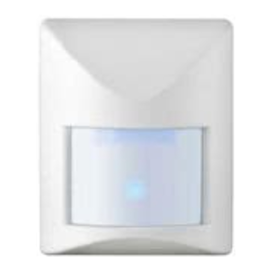
Copertura / Cover
Fig. 1
TECHNICAL CHARACTERISTICS
Pet Immunity with two-level animal size selection
IT
Nominal power voltage: ................... 12V
Consumption at 12 V : .................. 10mA nom. 17mA max.
Total IR coverage: ........................... 90° at 12 m
Sensitive zones: .............................. 18 on 4 floors
Alarm relay opto: ............................. 100mA / 24V
Tamperproof switch: ........................ 100 mA / 30V
Alarm time: ...................................... 3 sec
Working temperature range: ............ -10°C – +55°C
Ambient humidity: ............................ 95%
Theoretical MTBF: ........................... 120,000 HOURS
Dimensions (h x w x d): ................... 75 x 60 x 45 mm
Weight: ............................................ 65 g
Performance level: .......................... EN50131-2-2 Class II, Degree 2
OPTIONAL ACCESSORIES
• Detectors brackets Ref. 1033/119 *
CAUTIONS
• Install the sensor on rigid, vibration-free surfaces at a height comprised
between 2 and 2.3 metres making reference to the detection diagrams
• Avoid positioning the sensor close to sources of heat or direct sunlight.
• Avoid the creation of blind areas caused by furniture, shelving etc. in the
protected area in which an intruder could move about. Do no allow
animals to climb up anything (furniture, ladders etc.) and disturb the
sensitive part of the lens set for long-distance detection (see figure 2) or
the areas close to the sensor.
• Do not install the sensor outdoors.
• In case of installations at heights greater than 2.2 metres, it is advisable to
use the optional bracket (see details further on).
INSTALLATION
INSTALLATION
BRACKET
To remove the sensor cover,
remove the fastening screw (if
inserted)
and
press
screwdriver
on
screw towards the inside of the
slot. Widen one of the hooks E1-
E2 to remove the printed circuit
(Fig. 3).
Warning:
do not touch the
pyroelectric sensor with your
fingers.
Plastic bottom of the sensor (Fig.
3):
• A1-A2 = SET-UP FOR FIXING IN CORNER
• B1-B2 = SET-UP FOR FIXING ON FLAT SURFACE
• C1-C2-C3 = SET-UP FOR CABLE PASSING
Fix the plastic bottom to the wall with screws and anchor bolts being careful
that they do not touch the electronic board. Refit the circuit onto the plastic
terminato
cable passage) shown in Fig. 3, and assemble the bracket. Importantly,
after orienting, block the movement of the bracket by tightening the screw
provided with the bracket. The complete user manual of the bracket is
available on the website www.urmet.com.
+/- 3V
WITHOUT
with
a
the
fastening
bottom.
INSTALLATION WITH BRACKET - do not incline
downwards
to
maintain
function.
To install the bracket, open the specific cut-out
areas "D" (bracket fastening) and "C3" (bracket
Fig. 2
Fig. 3
EN
the
pet
immunity
Advertisement
Table of Contents

Related Manuals for urmet domus 1033/013


Summary of Contents for urmet domus 1033/013
- Page 1 DS1033-145D LBT20247 RIVELATORE IR CON PET IMMUNITY IR DETECTOR WITH PET IMMUNITY Fig. 3 Sch./Ref. 1033/013 CARATTERISTICHE TECNICHE TECHNICAL CHARACTERISTICS Pet Immunity con selezione della dimensione dell’animale su due livelli Pet Immunity with two-level animal size selection Tensione nominale di alimentazione: ... 12V +/- 3V Nominal power voltage: ....
- Page 2 DESCRIZIONE MORSETTIERA TERMINAL BOARD DESCRIPTION Da non utilizzare Not to be used Alimentazione 12V 12V power NC TAMP NC TAMP Contatto N.C. NC contact NC ALL Contatto N.C. del relè di allarme NC ALL NC alarm relay contact DESCRIZIONE DIPSWITCH DIP SWITCH DESCRIPTION DI FABBRICA I DIP SWITCHES SONO TUTTI OFF ALL DIP SWITCHES ARE SET TO OFF BY DEFAULT...
- Page 3 Abb. 2 ABDECKUNG DS1033-145D LBT20247 INFRAROT-MELDER PET IMMUNITY Abb. 3 Ref. 1033/013 TECHNISCHE EIGENSCHAFTEN INSTALLATION MIT GELENK - Nicht nach unten Haustierimmunitätsfunktion mit Auswahl der Haustiergröße auf zwei Ebenen kippen, um die Immunität gegenüber Tieren nicht zu verlieren. Nennspannung: ........12V +/- 3V Um die Verbindung zusammenzubauen, öffnen Sie...
- Page 4 ERSTE STROMVERSORGUNG Bei Stromversorgung tritt der Sensor in die Initialisierungsphase ein, während der die LED blinkt. Nach dieser Phase (die etwas 60 Sekunden dauert) wird der Sensor operativ. Den Leistungstest (Walk Test) wie folgt ausführen: Die Kunststoffblende anbringen und sich bei ausgeschalteter LED im vom Sensor kontrollierten Bereich bewegen und die Messung des PIR über die GELBE LED überprüfen.
Need help?
Do you have a question about the 1033/013 and is the answer not in the manual?
Questions and answers