urmet domus 1083 Manual
Hide thumbs
Also See for 1083:
- User manual ,
- Configuration booklet (152 pages) ,
- System booklet (100 pages)
Table of Contents
Advertisement
Quick Links
DS1083-137
Interactive Links
LIaaaaaaaaaaaa
Max. 32 apartment stations
per column
2Voice column
power supply unit
column
distributor
2Voice column
power supply unit
2Voice column
power supply unit
main calling stations
SYSTEM BOOKLET
calling
stations
door unit
interface
Max. 32 apartment stations
per column
2Voice column
power supply unit
column
distributor
Mod.
1083
LBT20922
calling
stations
Advertisement
Table of Contents

Related Manuals for urmet domus 1083


Summary of Contents for urmet domus 1083
- Page 1 Mod. 1083 DS1083-137 LBT20922 Interactive Links LIaaaaaaaaaaaa SYSTEM BOOKLET Max. 32 apartment stations Max. 32 apartment stations per column per column calling stations 2Voice column 2Voice column power supply unit power supply unit calling stations column distributor column distributor 2Voice column...
-
Page 2: Table Of Contents
Interactive Links The document contains INTERACTIVE LINKS for faster and more efficient consultation. INDEX 1. GENERAL CHARACTERISTICS AND INSTALLATION TYPES USING ONLY COLUMN POWER SUPPLY UNIT REF. 1083/2 ......................3 2. SYSTEM TYPOLOGIES ..........................4 3. SYSTEM OPERATION ..........................8 3.1 CALL AND BUSY STATE MANAGEMENT... -
Page 3: General Characteristics And Installation Types Using Only Column Power Supply Unit Ref. 1083/2
USING ONLY COLUMN POWER SUPPLY UNIT REF. 1083/23 The column power supply ref. 1083/23 can be used to make video door phone systems with up to 32 users per column (using a distributor or column interface), with up to 12 columns, each of which with up to 2 secondary calling stations. -
Page 4: System Typologies
• The system is intrinsically protected from static and pulse electromagnetic interference. SYSTEM TYPOLOGIES The systems described below can be made using only the column power supply unit Ref. 1083/23. Single column 1 riser 1 calling station LINE OUT... - Page 5 Single column max. 2 risers 2 main stations LINE OUT LINE IN main ID = 1 LINE main 2Voice column column ID = 0 power supply unit distributor ID = n Up to 12 columns 1 main calling station and 2 secondary stations for each column LINE OUT LINE OUT secondary...
- Page 6 12 columns 2 main calling stations and 2 secondary stations for each column LINE OUT LINE OUT LINE OUT secondary secondary secondary ID = n ID = n+1 ID = n+2 AUX dip 2 = 0 AUX dip 2 = 0 AUX dip 2 = 0 LINE IN LINE IN...
- Page 7 12 columns 2 main calling stations and 2 secondary stations for each column, concierge switchboard LINE OUT LINE OUT LINE OUT secondary secondary secondary ID = n ID = n+1 ID = n+2 AUX dip 2 = 0 AUX dip 2 = 0 AUX dip 2 = 0 LINE IN LINE IN...
-
Page 8: System Operation
SYSTEM OPERATION 3.1 CALL AND BUSY STATE MANAGEMENT The 2Voice system allows several conversations at the same time on different columns, in addition to a further conversation between main calling station and an apartment station belonging to any column not engaged by the conversation. The system works as follows when a call is made: • A call from a main call station switches all the other main calling stations and the entire column of the called apartment station to busy for a call pick-up time (max. -
Page 9: Video Surveillance And Access Control Functions
(terminals V3, V5). Up to 5 cameras connected to the calling station may be used with a video switching device 1038/69 or 1083/69. The user can press the button to cyclically view the images of the surveillance cameras on the main calling station with ID equal to 0, then in sequence the images of other main calling stations, finally the cameras of the secondary stations of the column to which it belongs. -
Page 10: Additional Functions
If there are several apartment stations in parallel, the extensions will ring in sequence. The user’s extension 0 will also switch the video door phone if the call comes from a video door phone station. In this case, during the call pick-up time (60s from the call), the video door phones of the other extensions can be switched on by pressing the auto-on button (video switching function) until one of the called user’s video door phones picks up. -
Page 11: System Installation
The installation of the Ref. 1083/23 is possible ONLY in an electrical panel. All devices comply with EC Standards with regards to electromagnetic compatibility and electrical safety. Furthermore, the power supply unit is IMQ and VDE certified. The system guarantees good noise immunity only if a Urmet... - Page 12 Maximum 12 distributors in Maximum 8 distributors per video door systems with column column in video door systems with derived from 1083/23 column derived from 1083/50 or / 53 Max. 48 apartment stations Max. 32 apartment stations per column per column Max.
-
Page 13: System Power
In this case, disconnect the connection between the “ILL” terminals of the calling station and the button module. • System with 12 columns (12 column distributors Ref. 1083/53 or column interfaces Ref. 1083/50): add 1 power supply unit for each column. -
Page 14: Allowed Cables
5.4 ALLOWED CABLES The 2VOICE bus is NON polarized. The cable (Ref.1083/90 or Ref.1083/94) has been designed to ensure the maximum distance and dimensions of the system. Because this cable is twisted, a good noise immunity is ensured. - Page 15 Cable the riser is derived 1083/23 1083/53 or /50 A+Bc 2Voice cable Ref. 1083/92 600m 600m 2Voice cable Ref. 1083/94 375m 375m Ø 0,6mm telephone pair without sheath 300m 300m CAT5 UTP (one twisted pair)
- Page 16 For connection and distances of the riser, see the paragraph “Door phone risers connection” extension distance Cable 2Voice cable Ref. 1083/92 600m 800m 2Voice cable Ref. 1083/94 375m 800m Ø 0,6mm telephone pair without sheath...
- Page 17 For connection and distances of the riser, see the paragraph “Door phone risers connection”. distance extension Cable call station column 400m 800m 800m 2Voice cable Ref. 1083/92 250m 500m 800m 2Voice cable Ref. 1083/94 200m 400m 600m Ø 0,6mm telephone pair without sheath...
- Page 18 Cable video riser is derived 1083/23 1083/53 or /50 A+Bv Colour 200m 200m 2Voice cable Ref. 1083/92 200m 200m 2Voice cable Ref. 1083/94 Colour 125m 125m Colour 150m 150m Ø 0,6mm telephone pair without sheath 125m 125m...
- Page 19 Bv = distance between the device from which the riser is derived and the most distant apartment station No. of apartment distance Cable video stations Colour 200m 2Voice cable Ref. 1083/92 200m 2Voice cable Ref. 1083/94 Colour 125m Colour 190m Ø 0,6mm telephone pair without sheath...
- Page 20 For connection and distances of the riser, see the paragraph “Video door phone risers connection”. distance extension Cable video Colour 200m 800m 2Voice cable Ref. 1083/92 200m 800m 2Voice cable Ref. 1083/94 Colour 125m 800m Colour 100m 600m Ø 0,6mm telephone pair without sheath...
- Page 21 Dx = distance between the door units interface and the power supply For connection and distances of the riser, see the paragraph “Video door phone risers connection”. distance extension Cable call station column 2Voice cable Ref. 1083/92 200m 400m 800m 2Voice cable Ref. 1083/94 125m 250m 800m Ø...
- Page 22 Cable 2Voice cable Ref. 1083/92 200m 2Voice cable Ref. 1083/94 125m For distances and extension of each column, see paragraph “Devices derived from a column interface with one or two video door phone call stations”. Street side branch connection split on the 4 outputs of door units interface Max 12 distributor...
- Page 23 Max. total number of distance extension distributors or column Cable interfaces G1+G2 Max 12 2Voice cable Ref. 1083/92 400m 1200m Max 12 2Voice cable Ref. 1083/94 250m 750m For distances and extension of each column, see paragraph “Devices derived from a column distributor or a column interface with one or two video door phone calling stations”.
-
Page 24: Electrical Door Lock Connection
Number of Street side distance Cable 4-user distributors or branch extension distributors column interfaces H+L1+L2+...+L12 2Voice cable Ref. 1083/92 Max 3 Max 12 200m 800m 2Voice cable Ref. 1083/94 Max 3 Max 12 125m 725m For distances and extension of each column, see paragraph “Devices derived from a column distributor or a column interface with one or two video door phone calling stations”. -
Page 25: Apartment Station Signal Connection
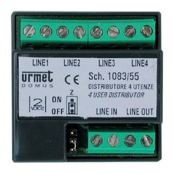
• Remove the sheath for the length needed to separate the pair in the two-wire line only. • Do not add electrical nodes to connect the devices. Use the device terminals only. Fit a 4/-user video distributor Ref. 1083/55 to connect an extension apartment unit to a riser column that does not cross the apartment. -
Page 26: Activating The System
LINE Z= ON LINE Z= ON LINE IN LINE OUT LINE IN LINE OUT LINE IN Z= OFF 1083/53 LINE 1 LINE 2 From calling LINE 4 LINE 3 station LINE Z= ON Z= ON Refer to the corresponding instruction booklets provided with the products for identifying the position of the line termination jumper in the various devices. -
Page 27: Line Termination Settings (Z)
6.1 LINE TERMINATION SETTINGS (Z) Refer to the previous chapter for correct Z line termination settings. Default settings All door phones are configured by default with line termination on. All brackets are configured by default with line termination on. All distributors are configured by default with line termination off. All column interfaces are configured by default with line termination on (jumper between Z terminal present). The line terminal on/off jumper (Z) is not present on some video door phones (e.g. 1750/1, 1750/5, 1750/6, 1750/15, 1750/16 and 1760/6). In this manner, in the typical case of system with calling station connected directly to the power supply unit and apartment stations connected as floor extensions to a column, only the jumper of the termination of the last distributor needs to be changed to the ON position. - Page 28 • There must not be two main stations with the same ID. Two secondary stations may coexist with the same ID but with different address (0 or 1). • The ID of the secondary door unit must coincide with the column ID set on the column distributor 1083/53 or column interface 1083/1083, if present.
- Page 29 Camera lights: the camera lights may be turned off if illumination in the surrounding environment is sufficient at night. Station type Main Secondary Secondary Secondary 0 Secondary 1 station address Door opener Door opener Door opener free privacy Interruption Camera Camera Camera lights lights lights DOOR OPENING TIME The position of the rotary switch (DOOR TIME) determines the activation time of the door lock.
- Page 30 USER 0 USER 1 USER 2 USER 3 USER 4 USER 5 USER 6 USER 7 USER 8 USER 9 USER 10 USER 11 USER 12 USER 13 USER 14 USER 15 USER 16 USER 17 USER 18 USER 19 USER 20 USER 21 USER 22...
- Page 31 USER 66 USER 67 USER 68 USER 69 USER 70 USER 71 USER 72 USER 73 USER 74 USER 75 USER 76 USER 77 USER 78 USER 79 USER 80 USER 81 USER 82 USER 83 USER 84 USER 85 USER 86 USER 87 USER 88...
-
Page 32: Power-On And Power Voltage Test
Ref. 1083/53 with the exception of the following constraints: The column distributor Ref. 1083/53 may be replaced by a column interface Ref. 1083/50 if there are up • to 2 risers in the system on the column (LINE 1 and LINE 2). -
Page 33: Check The System
The column distributor Ref. 1083/53 excludes and inserts line terminations through the Jumper Z. Disconnect the starting side and not the arrival side. 2. Fit a termination (Z in the ON position) on the last device connected to the riser column if a section connected in in-out mode is disconnected. -
Page 34: Associating Door Unit Buttons To Users
3. The termination of the last distributor must be inserted if a segment connected by means of distributors is disconnected. Z= ON Z= ON LINE IN LINE IN LINE OUT LINE OUT Z= OFF Z= ON LINE IN LINE IN LINE 1 LINE OUT LINE 2... - Page 35 Example: • System with 3 columns, the first with 4 users, the second with 6 users and the third with 8 users. • Access advanced configuration. • Set the ID dip-switch to 0. • Press the upper button of the door unit (first button). • Set the ID dip-switch to 1. • Press third button of the first button module (fifth button) to associate user 0 of column 1 in this manner. • Set the ID dip-switch to 2. • Press first button of the third button module (eleventh button) to associate user 0 of column 2 in this manner.
-
Page 36: Basic Functional Test
“B” Secondary call module with 8 buttons ID = n AUX dip 2 = 1 offset = 11 Called users: from 11 to 18 Secondary call module with 11 buttons ID = n AUX dip 2 = 0 2Voice column offset = 0 power supply interface... - Page 37 1 surveillance camera 1 surveillance camera 2 surveillance cameras 2 surveillance cameras 3 surveillance cameras 3 surveillance cameras 1038/69 or 1083/69 1038/69 or 1083/69 4 surveillance cameras 4 surveillance cameras 1038/69 or 1083/69 1038/69 or 1083/69 5 surveillance cameras...
- Page 38 – Press the button to be programmed for at least 3 seconds, until the confirmation tone sounds. – Go to the user who will be called by pressing the button (user B) and press the door opener button. The apartment stations will be beep to indicate that they have been programmed. – Alternatively, go to a calling station and press the calling button of user B. The apartment station being programming (A) will beep to indicate that it has been programmed.
- Page 39 INTERCOM FUNCTION IN THE SAME APARTMENT Go to the apartment station to be programmed as caller (apartment station C1). There are two different ways to enter programming state (check which method is used on the instruction booklet supplied with the product): 1b) With dedicated button (Miro and Vmodo).
-
Page 40: Technical Specifications Of The Devices
Working temperature range:......................- 5 ÷ + 45 °C Dimensions: ........................... 45 x 45 x 16 mm Column power supply unit Ref. 1083/23 Power supply in CAT II 2500 V. Once installed, the power supply is subject to transient voltages higher than those of the overvoltage category for which is was designed. -
Page 41: Notes On Diagrams
NOTES ON DIAGRAMS C4.013 Fit a 9V (MN1604/6LR61) battery in the VX.037 On device setting the jumper/dip-switch ringer. The ringer is equipped with two “Z” in position “ON”. jumpers indicated by W1 and W2. Remove one of the two jumpers for two-tone V2.003 Switch the line termination “Z” to the off or one-tone operation as shown in the position (see instruction booklet provided following table: with the product). - Page 42 Connection of 1 column with N video door phones to 1 video entrance panel (VPE). SV124-1353 “COLUMN” Ref.1083/55 4-USER DISTRIBUTOR TO THE NEXT DISTRIBUTORS Ref.1083/55 4-USER DISTRIBUTOR TO NEXT MODULES RINGER MAX. 4 EXPANSION CIRCUITS 16 USERS NAME TAG LIGHTING Ref.1083/23...
- Page 43 BACKBONE “1” LINE OUT LINE LINE LINE LINE LINE (VD.007) LINE LINE LINE LINE LINE LINE IN (VD.007) (VD.007) Ref.1083/55 4-USER DISTRIBUTOR (VX.037) Ref.1072/59 ADDITIONAL RINGER (C4.013) TO THE NEXT DISTRIBUTORS LINE OUT LINE LINE LINE LINE LINE LINE (VD.007) (VD.007)
- Page 44 LINE LINE LINE LINE LINE LINE LINE LINE LINE LINE IN LINE IN (VD.007) (VD.007) (VD.007) (VD.007) Ref.1083/55 Ref.1083/55 4-USER 4-USER DISTRIBUTOR DISTRIBUTOR (VV.001) (VV.001) RINGER RINGER (C4.013) (C4.013) AS BACKBONE “1” AS BACKBONE “1” TO THE NEXT TO THE NEXT...
- Page 45 COLUMN “2” BACKBONE “3” BACKBONE “4” EQUIPMENT/CONNECTIONS BACKBONES “3-4” AS BACKBONE “1” Ref.1083/5X 2VOICE COLUMN DISTRIBUTOR OR COLUMN INTERFACE (VX.021) LINE 2 LINE 1 IN 0 IN 1 LINE LINE POWER SECONDARY “III” SECONDARY “IV” AS “MAIN” AS “MAIN” VIDEO OUTDOOR STATION VIDEO OUTDOOR STATION Ref.1083/23...
- Page 46 Connection of N columns with 2 risers each with N video door phones with 2 main video door phones. Furthermore, each group is connected to 1 or 2 secondary video door units. SV124-1356 COLUMN “1” BACKBONE “1” BACKBONE “2” Ref.1083/55 4-USER DISTRIBUTOR RINGER (C4.013) TO THE NEXT DISTRIBUTORS AS BACKBONE “1”...
- Page 47 COLUMN “2” BACKBONE “3” BACKBONE “4” EQUIPMENT/CONNECTIONS BACKBONES “3-4” AS BACKBONE “1” Ref.1083/5X 2VOICE COLUMN DISTRIBUTOR OR COLUMN INTERFACE (VX.021) TO THE DISTRIBUTORS OR COLUMN INTERFACES OF THE SUBSEQUENT GROUPS SECONDARY “III” SECONDARY “IV” AS MAIN “A” AS MAIN “A”...
- Page 48 Replacement of the push-button panel mod. Sinthesi S2 with push-button panel mod. Sinthesi Steel or mod. Alpha. Sinthesi S2 TO FOLLOWING MODULES Sinthesi Steel MAX. 4 EXPANSION INPUT CIRCUITS 16 USERS Cable 'B' or 'A' (VX.006) Output Input OUTPUT INPUT OUTPUT VIDEO VIDEO...
- Page 49 Example of connection for activation of an additional electric lock in parallel with the system one SV124-1029C A) Manual command for electric lock simultaneous activation. LINE TO THE SYSTEM LINE TO THE SYSTEM RELAY BOX LOCK Sch.788/52 RELEASE (VX.008) TRANSFORMER ~230 RELAY BOX Ref.9000/230...
- Page 50 SV124-1024C Example of call repeat with relay box Ref. 788/52. LINE LINE (VD.007) ~230 (VD.007) LINE ~ Ref.9000/230 ~230 (VX.008) LINE ~ Ref.9000/230 (VX.008) LOAD 100V=/5A LOAD 100V=/5A POWER POWER Ref.788/52 Ref.788/52 Example of call repeat with relay box Ref. 788/22. LINE LINE (VD.007)
- Page 51 The video door phones are Mod. 1750, for example: A) Ref. 1750/1 B) Ref.1750/1 with Ref. 1750/50 accessory The door phones are Mod. 1150. All devices must have the same external calling code. The Master device internal code must be 0. TO RISER COLUMN Ref.1083/55 4 USER DISTRIBUTOR LINE LINE OUT LINE LINE...
- Page 52 WARNING The line terminal on/off jumper (Z) is not present on some video door phones (e.g. 1750/1, 1750/5, 1750/6, 1750/15, 1750/16 e 1760/6). Consequently, the in-out connection can only be implemented by adding the Ref. 1750/50 accessory, which must be installed in the device preceding the end- of-line device in the specific housing on the back of the video door phone. Ref.
Need help?
Do you have a question about the 1083 and is the answer not in the manual?
Questions and answers