
Related Manuals for Fike FIK-IR3-AS25


Summary of Contents for Fike FIK-IR3-AS25
- Page 1 FIK-IR3 User Manual Doc. No. 06-929.02 FIK-IR3 Triple IR Flame Detector 704 SW 10 Street, Blue Springs, MO 64014, USA T: (+1) 816-229-3405 www.fike.com...
- Page 3 The Fike logo is a trademark of Fike Corporation, registered in the U.S. and other countries. Every effort has been made to ensure that the information in this manual is accurate. However, Fike is not responsible for any inaccuracy or omission in this document. The information in this document is subject to...
-
Page 4: Table Of Contents
Modbus Address ............................9 3.7. Manual BIT – Alarm Output Test ........................9 Detector Wiring ..............................10 4.1. Wiring Functions: ............................10 4.2. Current Output (0-20mA) Wiring ....................... 11 4.3. RS-485 Communication Network ....................... 13 For more information & Technical support: (800)-979-FIKE (3453) - Page 5 Ex db ..............................19 6.7. Approvals ..............................20 6.8. Electromagnetic Compatibility ........................20 Warranty ................................21 Appendix A Response Characteristics ....................... 22 Response to different fire scenarios ......................22 False Alarm Immunity ..........................23 For more information & Technical support: (800)-979-FIKE (3453)
- Page 6 Figure 8: RS-485 Networking ............................13 List of Tables Table 1: DETECTOR CONFIGURATION OPTIONS ......................8 TABLE 2: SENSITIVITY LEVELS ............................8 TABLE 3: TERMINAL CONNECTIONS ..........................10 TABLE 4: OUTPUT SIGNALS ............................14 For more information & Technical support: (800)-979-FIKE (3453)
-
Page 7: Introduction
Table 4 (in section 5.1). During “Dirty Window” fault the detection sensitivity is significantly reduced, while “Fault” refers to critical faults which totally prevent flame detection. For more information & Technical support: (800)-979-FIKE (3453) -
Page 8: Installation
The nature of the hazards, including materials stored or used and the protected objects • The sensitivity of the detectors • • If there are any obstructed lines of sight • The field of view of the detectors For more information & Technical support: (800)-979-FIKE (3453) -
Page 9: Preparations For Installation
• Use wire rated for a temperature of at least 111°C, which is 5°C above the rated service temperature. For more information & Technical support: (800)-979-FIKE (3453) -
Page 10: Required Tools
The equipment is not intended to be repaired by the user. Repair of this equipment shall be carried out by the manufacturer in accordance with the applicable code of practice. • The flameproof joints are not intended for repair. Contact the manufacturer if the flameproof joints are damaged. For more information & Technical support: (800)-979-FIKE (3453) -
Page 11: Installing The Tilt Mount
0.28" (7mm) diameter holes. There are four captive screws with spring washers in the tilt mount. The following drawing shows the location of the four holes for the screws and washers. Figure 1: Tilt Mount Base - Rear View For more information & Technical support: (800)-979-FIKE (3453) -
Page 12: Installing The Detector
The detector is now correctly located, aligned and ready to be connected to the system. Please refer to section 0 for wiring instructions, and section 3 for a description of the detector’s configuration settings. For more information & Technical support: (800)-979-FIKE (3453) -
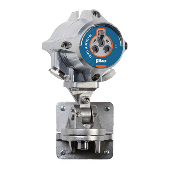
Page 13: Figure 3: Detector On Tilt Mount - Side View
: Detector on Tilt Mount – Side View ITEM ITEM NAME TILT MOUNT ASSEMBLY HOLDING PLATE MOUNTING HEX SCREWS M8 AND LOCK WASHERS HEX SOCKET LOCKING SCREW M8 HEX SOCKET LOCKING SCREW M12 For more information & Technical support: (800)-979-FIKE (3453) -
Page 14: Configuration Options
100 (30) High 200 (60) Extreme 260 (80) A standard fire is defined as a 1x1 ft (0.1 m ) N-heptane pan fire, with maximum wind speed of 6.5 ft/s (2 m/s). For more information & Technical support: (800)-979-FIKE (3453) -
Page 15: Ultra-Fast Detection
BIT is initiated and the “Manual BIT – Alarm Output Test” is enabled as the Manual BIT will set the 0-20mA terminal to 20mA and close the alarm relay. For more information & Technical support: (800)-979-FIKE (3453) -
Page 16: Detector Wiring
Shield This terminal should be left connected to the housing internal ground screw. RS 485 (+) RS-485 Modbus communication (used by the “Communicator” software) RS485 (-) Fault Relay (NC) Alarm Relay (NC) For more information & Technical support: (800)-979-FIKE (3453) -
Page 17: Current Output (0-20Ma) Wiring
Figure 4: Source 4-Wire Scheme The following drawing shows how to wire the detector to act as a current sink isolated transmitter (4-wire connection): Power Return Detector Controller Return Figure 5: Sink 4-Wire Scheme For more information & Technical support: (800)-979-FIKE (3453) -
Page 18: Figure 6: Source 3-Wire Scheme
Figure 6: Source 3-Wire Scheme The following drawing shows how to wire the detector to act as a current sink non-isolated transmitter (3- wire connection): 24 VDC Return Detector Controller Figure 7: Sink 3-Wire Scheme For more information & Technical support: (800)-979-FIKE (3453) -
Page 19: Rs-485 Communication Network
BIT to each detector individually. The detector communicates via RS-485 with a Modbus RTU compatible protocol. For more details on the communication protocol, please consult with FIKE. Figure 8: RS-485 Networking For more information & Technical support: (800)-979-FIKE (3453) -
Page 20: Operation
VDC (-)“ terminal for one second (see Table 3) or by using the communicator software (connected through RS-485). In case of “Dirty Window” fault the detector may still detect flames but at a lower sensitivity. For more information & Technical support: (800)-979-FIKE (3453) -
Page 21: Maintenance
Where dust, dirt or moisture accumulates on the window, first clean the window with a soft optical cloth and detergent, and then rinse with a clean soft cloth, cotton swab, or tissue. For more information & Technical support: (800)-979-FIKE (3453) -
Page 22: Troubleshooting
Alarm Relay closed and Detector is exposed • current output is at 20mA to a flame If caused by “friendly fire”, • reposition the detector so that it is not affected by it. For more information & Technical support: (800)-979-FIKE (3453) -
Page 23: Specifications
Modbus RTU compatible protocol on RS-485 The FAULT relay will normally be energized and the contact will be closed during normal operation of the detector. The contact will be open at fault condition or low voltage. For more information & Technical support: (800)-979-FIKE (3453) -
Page 24: Mechanical Specifications
-67°F to + 185°F (-55°C to +85°C) • Storage -67°F to + 185°F (-55°C to +85°C) Humidity: up to 99%, non-condensing • • Ingress Protection: IP66 & 68 (2m, 24hr); NEMA 4X & 6P For more information & Technical support: (800)-979-FIKE (3453) -
Page 25: Label Figures
FIK-IR3 User Manual Doc. No. 06-929.02 6.6. Label Figures 6.6.1. Ex db For more information & Technical support: (800)-979-FIKE (3453) -
Page 26: Approvals
The detector fully complies with EMC directive 2014/30/EU and protected against interference caused by RFI and EMI. The cables to the detector must be shielded and the detector must be grounded in order to comply to the EMC directive. For more information & Technical support: (800)-979-FIKE (3453) -
Page 27: Warranty
Doc. No. 06-929.02 7. Warranty FIKE CORPORATION agrees, to the extent allowed by applicable law, to transfer and pass through to Purchaser/Distributor the following original manufacturer’s warranty from FIRE & GAS DETECTION TECHNOLOGIES INC., manufacturer and supplier of the FlameSpec products: FIRE & GAS DETECTION TECHNOLOGIES INC. -
Page 28: Appendix A Response Characteristics
Pan Size Distance ft (m) Average Response Time (Seconds) N-Heptane 1 x 1 ft 197 (60) 32-in Plume 148 (45) 1 x 1 ft 148 (45) Methanol 1 x 1 ft 125 (38) For more information & Technical support: (800)-979-FIKE (3453) -
Page 29: False Alarm Immunity
For each radiation source a distance is listed. This is the minimum tested distance, from which the detectors did not alarm when exposed to the radiation source (either modulated or non-modulated). For more information & Technical support: (800)-979-FIKE (3453) - Page 30 Projector led 2 (0.5) Solenoid bell 2 (0.5) Soldering iron 2 (0.5) Electric Drill 2 (0.5) Contact us Fike Corporation 704 SW 10 Street, Blue Springs, MO 64014, USA Tel: (+1) 816-229-3405 www.Fike.com For more information & Technical support: (800)-979-FIKE (3453)
Need help?
Do you have a question about the FIK-IR3-AS25 and is the answer not in the manual?
Questions and answers