Advertisement
INSTALLATION AND MAINTENANCE INSTRUCTIONS
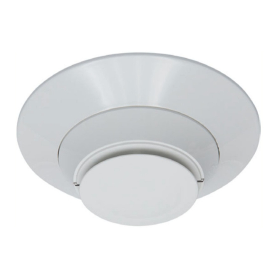
FIK-2351
Intelligent Photoelectric Smoke Sensors
SPECIFICATIONS
Operating Voltage Range:
15 to 32 VDC
Operating Current @ 24 VDC: 200 uA (one communication every 5 sec. with green LED blink on communication)
Maximum Alarm Current:
2 mA @ 24 VDC (one communication every 5 seconds with red LED solid on)
Maximum Current:
4.5 mA @ 24 VDC (one communication every 5 seconds with amber LED solid on)
Operating Humidity Range:
10% to 93% Relative Humidity, Non-condensing
Operating Temperature Range: 32°F to 122°F (0°C to 50°C)
Air Velocity:
0 to 4000 ft./min. (0 to 1219.2 m/min.)
Height:
2.0˝ (51 mm) installed in B300-6 Base
Diameter:
6.2˝ (156 mm) installed in B300-6 Base; 4.1˝ (104 mm) installed in B501 Base
Weight:
3.4 oz. (95 g)
Isolator Load Rating:
0.0063*
*Please refer to your isolator base/module manual for isolator calculation instructions.
UL 268 listed for Open Air Protection.
UL268A listed for Duct Applications.
This sensor must be installed in compliance with the control panel system
installation manual. The installation must meet the requirements of the Au-
thority Having Jurisdiction (AHJ). Sensors offer maximum performance when
installed in compliance with the National Fire Protection Association (NFPA);
see NFPA 72.
GENERAL DESCRIPTION
FIK-2351 is a plug-in type smoke sensor that combines a photoelectronic sens-
ing chamber with addressable-analog communications.
The sensors transmit an analog representation of smoke density over a com-
munication line to a control panel. Rotary dial switches are provided for set-
ting the sensor's address. (See Figure 1.)
FIGURE 1. ROTARY ADDRESS SWITCHES
7
8
6
9
5
10
4
3
13
2
14
1 0
15
TENS
Two LEDs on the sensor are controlled by the panel to indicate sensor status.
An output is provided for connection to an optional remote LED annunciator
(P/N RA100Z).
Fike panels offer different feature sets across different models. As a result,
certain features of the photoelectric sensors may be available on some control
panels, but not on others. These devices support Fike IDP mode systems. The
possible features available if supported by the control panel include:
1. The sensor's LEDs can operate in three ways—on, off, and blinking–and
they can be set to red, green, or amber. This is controlled by the panel.
2. The remote output may be synchronized to the LED operation or con-
trolled independent of the LEDs.
3. Devices are point addressable up to 159 addresses.
Please refer to the operation manual for the UL listed control panel for specific
operation. The photoelectric sensors require compatible addressable com-
munications to function properly. Connect these sensors to listed-compatible
control panels only.
SPACING
Fike recommends spacing sensors in compliance with NFPA 72. In low air
flow applications with smooth ceilings, space sensors 30 feet apart (9.1 m).
For specific information regarding sensor spacing, placement, and special ap-
plications, refer to NFPA 72 or the System Smoke Detector Application Guide,
available from System Sensor.
Duct Applications: FIK-2351 is listed for use in ducts. See Duct Smoke De-
tectors Applications Guide HVAG53 for details on pendant mount applications.
NOTE: Intelligent photoelectric smoke sensors are also listed for use inside
DNR(W) duct smoke detectors.
7
8
6
9
5
11
4
12
3
2
1 0
ONES
WIRING GUIDE
All wiring must be installed in compliance with the National Electrical Code,
applicable local codes, and any special requirements of the Authority Having
Jurisdiction. Proper wire gauges should be used. The installation wires should
be color-coded to limit wiring mistakes and ease system troubleshooting. Im-
proper connections will prevent a system from responding properly in the
event of a fire.
Remove power from the communication line before installing sensors.
1. Wire the sensor base (supplied separately) as shown in the wiring
diagram. (See Figure 2.)
2. Set the desired address on the sensor address switches. (See Figure 1.)
3. Install the sensor into the sensor base. Push the sensor into the base while
turning it clockwise to secure it in place.
4. After all sensors have been installed, apply power to the control panel and
activate the communication line.
5. Test the sensor(s) as described in the TESTING section of this manual.
Dust covers provide limited protection against airborne dust particles during
shipping. Dust covers must be removed before the sensors can sense smoke.
C0162-00
Remove sensors prior to heavy remodeling or construction.
FIGURE 2. WIRING DIAGRAM
Remote
Annunciator
+
(+)
+
2
RA
3
(–)
(–)
CLASS A OPTIONAL WIRING
(+)
TAMPER-RESISTANCE
Intelligent photoelectric smoke sensors include a tamper-resistant capability
that prevents their removal from the base without the use of a tool. Refer to
the base manual for details on making use of this capability.
1
Blue Springs, MO 64015
Phone: 816.229.3405; Fax: 816.228.9277
For system/product documentation including
installation, operation, and maintenance,
scan QR code or enter URL provided.
http://www.fike.com/06-912
CAUTION
CAUTION: Do not loop wire under
terminal 1 or 2. Break wire run to
-
supervise connections.
+
+
+
–
2
–
RA
1
1
3
R
704 SW 10th Street
www.fike.com
+
+
2
–
RA
1
3
C0129-10
I56-6632-001
10/5/2021
Advertisement
Table of Contents

Related Manuals for Fike FIK-2351


Summary of Contents for Fike FIK-2351
- Page 1 NFPA 72 or the System Smoke Detector Application Guide, available from System Sensor. Duct Applications: FIK-2351 is listed for use in ducts. See Duct Smoke De- tectors Applications Guide HVAG53 for details on pendant mount applications. NOTE: Intelligent photoelectric smoke sensors are also listed for use inside DNR(W) duct smoke detectors.
- Page 2 – Connect the equipment into an outlet on a circuit different from that to which the receiver is con- Limitations of nected. Fire Alarm Systems – Consult the dealer or an experienced radio/TV technician for help. Fike ® is a registered trademark of Fike Corporation. System Sensor® is a registered trademark of Honeywell International, Inc. I56-6632-001 ©2021. 10/5/2021...
Need help?
Do you have a question about the FIK-2351 and is the answer not in the manual?
Questions and answers