Table of Contents
Advertisement
Quick Links
edition
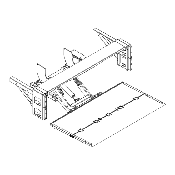
DH-RP.12
INSTALLATION MANUAL
1200kg
** Pictured: RP.12 tail lift
Manufacturer:
DHOLLANDIA N.V.
Zoomstraat 9
9160 LOKEREN (Belgium)
Tel : +32 (0)9 349 06 92
Fax : +32 (0)9 349 09 77
e-mail : info@dhollandia.be
website : www.dhollandia.com
Read the manual in its entirety before operating the tail lift
Keep this manual in the vehicle cab, as reference for the driver and tail lift operator
Doc: FIT_RP.12_CE_EN_2020_rev0
Rev: 0 Date: JANUARY 1, 2020
Advertisement
Table of Contents

Related Manuals for Dhollandia DH-RP.12


Summary of Contents for Dhollandia DH-RP.12
- Page 1 9160 LOKEREN (Belgium) Tel : +32 (0)9 349 06 92 Fax : +32 (0)9 349 09 77 e-mail : info@dhollandia.be website : www.dhollandia.com Read the manual in its entirety before operating the tail lift Keep this manual in the vehicle cab, as reference for the driver and tail lift operator Doc: FIT_RP.12_CE_EN_2020_rev0...
-
Page 2: Table Of Contents
CONTACT INFORMATION ................................4 SAFETY PRECAUTIONS FOR OPERATION ..........................5 SAFETY PRECAUTIONS FOR INSTALLATION ........................... 5 TAIL LIFT TERMINOLOGY ................................8 DH-RP.12 Tail lift terminology ............................... 8 Installation parameters terminology ............................ 10 Getting started ..................................13 Installation dimensions ................................ 14 FLOOR EXTENSION PLATE AND CHASSIS CUT ........................ -
Page 3: Understanding Safety And Warning Signs
Many safety signs and symbols used in this manual are based on international standards, others refer to specific situations or actions. Consult Appendix 1 for an overview of signs and symbols used in DHOLLANDIA manuals, and their meaning. Make sure you understand these signs and symbols prior to starting the installation. Examples of standard ANSI... -
Page 4: Introduction And Disclaimers
Prior to operating the tail lift, make sure you understand the safety and warning signs used, and read them in conjunction with the instructions in this manual. If in doubt, DO NOT operate the tail lift. Contact your national DHOLLANDIA distributor. See page 5 for contact info. 2 INTRODUCTION AND DISCLAIMERS ... -
Page 5: Contact Information
Contact your national DHOLLANDIA distributor if you have any questions regarding the installation, operation, repair and maintenance of DHOLLANDIA tail lifts, to obtain replacement copies of manuals or decals, or to learn about available equipment options for DHOLLANDIA tail lifts. -
Page 6: Safety Precautions For Operation
These instructions are supplied as a separate manual with your tail lift. You can also contact the national DHOLLANDIA distributor for the latest edition of this manual. See page 5 for contact info. Or download the latest edition from the website: www.dhollandia.com →... - Page 7 DHOLLANDIA tail lift. In case of doubt, ALWAYS contact the national DHOLLANDIA distributor for further advice, prior to continuing. ALWAYS wear appropriate Personal Protective Equipment. This includes but may not be limited to: ANSI rated glasses with side guards, or a wrap-around face shield;...
- Page 8 Except for the support channels and bracing of the side steps, which are usually welded to the cross members of the auxiliary chassis, DHOLLANDIA tail lifts are designed as a bolt-on system, and don’t require any welding. See Appendix 2 for prescribed torque values.
-
Page 9: Tail Lift Terminology
6 TAIL LIFT TERMINOLOGY DH-RP.12 TAIL LIFT TERMINOLOGY See Figure 6.1 on next page for parts corresponding to numbers in this table Description Platform Assembly: combination of the main and flip sections of the platform. Platform, Main Section: inboard section of the foldable platform. Manufactured from steel or lightweight aluminium, with a permanent non-slip working surface. - Page 10 Figure 6.1 DHOLLANDIA...
-
Page 11: Installation Parameters Terminology
Maximum length of the main and foldable platform sections [= Platform Depth] Required mounting space to end of lift frame [= Lift Overhang to Frame] Required mounting space to end of premounted pump unit [= Lift Overhang to Pump unit] DHOLLANDIA... - Page 12 Figure 6.2 DHOLLANDIA...
- Page 13 See Figure 6.3 for parts corresponding to numbers in this table: Width of the lift arms [= Lift Arm Centre] Vehicle chassis width [= CHassis Width] Min. body width with pump unit in premounted position [= Body Width Outside] Figure 6.3 DHOLLANDIA...
-
Page 14: Getting Started
/ or body will not adversely affect the structural integrity of the chassis and / or body. In the event instructions of vehicle manufacturer conflict with the installation instructions issued by DHOLLANDIA (e.g. on fuse ratings, etc.), contact your national DHOLLANDIA distributor for further assistance. ... -
Page 15: Installation Dimensions
(e.g. to suspension, braking system, hydraulic and electrical circuits, etc.). INSTALLATION DIMENSIONS The DH-RP.12 is usually delivered with a premounted mounting bar between the lift arms and lift frame, pre-setting the mounting height MFT = 445mm. [Figure 6.4] Figure 6.4 shows: 1. - Page 16 Figure 6.4 Dimensions table CTH MAX VFH MAX 1300 VFH MIN 1064 LARM Figure 6.5 DHOLLANDIA...
- Page 17 If you decide to remove the mounting bar and change the mounting height MFT of the tail lift, ensure to stay within the applicable ranges for the installation parameters VFH, MFT and MTG. Consult the national DHOLLANDIA distributor for confirmation of max. and min. mounting dimensions and obtain a chassis cut-out drawing for the new mounting height MFT. ...
-
Page 18: Floor Extension Plate And Chassis Cut
The installation can be a STANDARD MOUNT [see Figure 7.1] whereby the bed extension is added behind the rear sill of the vehicle body. Or it can be a FLUSH MOUNT [Contact DHOLLANDIA for guidance], whereby the bed extension is integrated into the vehicle floor. -
Page 19: Mounting Of The Extension Plate
Measure, mark and drill the 13 holes dia. 14.3mm required for mounting the extension, then coat the holes to protect against corrosion. Position the floor extension up to the rear sill using a fork lift or hoists. Figure 8.1 Dimensions table DHOLLANDIA... - Page 20 Ensure the extension plate is level with the vehicle floor [Figure 8.2]; and flush with the top surface of the rear sill. Then tighten the bolts to the required torque. Work from the centre outward. Figure 8.3 Total extension plate 11x M14x1.5 (10.9) 185 Nm DHOLLANDIA...
- Page 21 Before welding, note that welding on galvanized parts releases hazardous fumes. Provide adequate ventilation, and war an appropriate toxic fume rated welding respirator. It is strongly recommended to first grind off the galvanizing in areas where welding is to be done. DHOLLANDIA...
-
Page 22: Mounting Of The Lift Frame (Premounted Platform)
Therefore, handle the platform with care. Use lifting aids such as a forklift, gantry crane, hoists and clamps etc… to assist you through the unfolding movement. Mount the mounting plates on the lift frame and tighten the bolts by hand. [Figure 9.3] Each mounting plate is bolted to the lift frame by means of [Figure 9.3]: DHOLLANDIA... - Page 23 These brackets will help align the platform with the extension plate. [Figure 9.4]. Install a min. 136kg counter weight on the channels to prevent them from moving during installation. Or tack-weld the brackets temporarily to the rear sill and floor of the vehicle. DHOLLANDIA...
- Page 24 Hoist the platform and attached lift frame and place a hydraulic jack under the lift frame [Figure 9.5] Figure 9.5 DO NOT try to raise and hold the tail lift via the flip-over point. Affix hoists to the platform main section! DHOLLANDIA...
- Page 25 Ensure that the platform is centred in the centreline of the vehicle, and that it is flush and parallel with the extension plate. Secure the correct platform position by clamping the platform main section to the 76mm mounting tubes. [Figure 9.6] Figure 9.6 DHOLLANDIA...
-
Page 26: Fixation Of The Bolt-On Mounting Plates
Ensure the platform and lift frame are positioned in conformance with the mounting instructions and dimensions indicated in the installation drawing and manual, before drilling or welding the mounting plates to the chassis. It is not allowed to reduce the width of the mounting plates without prior written authorization from DHOLLANDIA. 10 FIXATION OF THE BOLT-ON MOUNTING PLATES ... - Page 27 Straighten the mounting plates, and make sure they stand perpendicular to the lift frame. Ensure the lift frame is correctly centred under the vehicle chassis and body. [Figure 10.1] The mounting plates MUST be bolted to the lift frame according to the instructions in Figure 9.6. Tighten the bolts and nuts with the prescribed torque. DHOLLANDIA...
- Page 28 The mounting plates are bolted to the vehicle chassis with min. 6 bolts M14 per side, supplied with the lift, spread over a widest possible surface to maximize the strength of the bolted connection. Fasten the 6 bolts M14 per side with the required torque Figure 10.2 Figure 10.2 Per side Min. 6x M14x1.5 (10.9) 185 Nm DHOLLANDIA...
- Page 29 If there is no overlap, add a connection plate to extend the height of the mounting plate, overlap the long sills, and make min. 2 pcs. 10mm welds, min. 102mm long, at the top of the mounting plates (per plate). Apply equivalent welds to join the mounting plate with the connection plate. [Figure 10.5]. Figure 10.4 DHOLLANDIA...
- Page 30 During installation, the bolts and nuts should be fastened to the proper torque, shown in these installation instructions. If you use mounting bolts not supplied by DHOLLANDIA, make sure the total strength is at least equivalent as per this manual. ...
-
Page 31: Installation Of Control Switch
Connect the wires of the cable to the connection points in the pump unit, as per wiring diagrams attached. g. Coil in the excess cable inside the pump unit. Fix and immobilize it with cable ties to the hydraulic return pipe of the valve block. DHOLLANDIA... - Page 32 The main wiring diagrams are included in the pages hereafter, and in the appendix. The wiring logic for the DH-RP.12 with power down function (ref. OAH025.01) is called DAD4 [Figure 11.4], and uses following abbreviations: R = starter solenoid for the DC motor...
- Page 33 Figure 11.4 Figure 11.5 DHOLLANDIA...
-
Page 34: Connection Block Terminology
S – Control valve (Close/Tilt up) in the power pack O – Electrical self-locking valves (Open/Tilt/Down) on the tilt cylinders I – Control valve (Slide In) in the power pack U – Control valve (Slide In) in the power pack DHOLLANDIA... -
Page 35: Gravity Down Wiring For The Control Switch
11.3 GRAVITY DOWN WIRING FOR THE CONTROL SWITCH The control switch and relay MUST be correctly wired to the connection block for proper operation. [Figure 11.7] Figure 11.7 To ground post on pump motor To positive post on motor solenoid DHOLLANDIA... - Page 36 For option OAE510.15, see Figure 11.8, below: Figure 11.8 To ground post on pump motor To positive post on motor solenoid DHOLLANDIA...
-
Page 37: Power Down Wiring For The Control Switch
11.4 POWER DOWN WIRING FOR THE CONTROL SWITCH The control switch and relay MUST be correctly wired to the connection block for proper operation. [Figure 11.9] Figure 11.9 To ground post on pump motor To positive post on motor solenoid DHOLLANDIA... - Page 38 For option OAE510.15, see Figure 11.10, below: Figure 11.10 To ground post on pump motor To positive post on motor solenoid DHOLLANDIA...
-
Page 39: Connection To The Batteries
12 CONNECTION TO THE BATTERIES A general schematic of how to correctly connect the batteries to the tail lift is provided in Figure 12.1. Figure 12.1 DHOLLANDIA... - Page 40 If not supplied with the tail lift, these can be downloaded from the “DOWNLOAD” section on our website: http://www.dhollandia.com Please confirm you have reviewed the most up-to-date version of this manual prior to continuing. ...
-
Page 41: Putting The Tail Lift Into Service
The installer should remain vigilant and stay out of the range of motion of the platform and the moving parts of the tail lift as long as the hydraulic circuits have not been purged. DHOLLANDIA... - Page 42 Adjust the length of the platform opener assembly. [Figure 13.3] It is usually pre-installed at the factory but needs fine-tuning during the installation. If removed, mount it back in its original position to avoid damaging the platform prior to unfolding and folding the platform. DHOLLANDIA...
-
Page 43: Platform Orientation
Falling cargo will put the operator and any bystanders at serious risk of bodily injury and death. Therefore, it is important that the pitch of the flip-over point and complete platform are adjusted correctly conform with instructions in this manual. DHOLLANDIA... - Page 44 Figure 14.1 Figure 14.2 DHOLLANDIA...
-
Page 45: Mounting Of The Side Steps & Dock Bumpers
3. Maintain a 90° angle between the steps and the extension plate. [Figure 15.3] 4. Fasten all bolts and locking nuts to the required torque settings. Figure 15.1 ❷ ❶ Per side 2x M16x2 (8.8) 195 Nm ❶ 2x M16x2 (8.8) 195 Nm ❷ DHOLLANDIA... - Page 46 3m overhang to the centre of the rear axle [fig. 17.4]. For cases with insufficient ground clearance, side steps with a flexible bottom step are available (option ref. OAM057.LR). Figure 15.3 Weld on inside and outside of channel Per side 2x M16x2 (8.8) 195 Nm DHOLLANDIA...
- Page 47 Where chassis beams, longs sills, the rear sill and other steel chassis or body components have been cut, grinded, drilled, welded etc…, the installer should apply adequate anti-corrosive coating to protect the vehicle and body against corrosion. Check, and make sure you comply with the instructions of the OEM vehicle manufacturer. DHOLLANDIA...
-
Page 48: Lubrication Instructions
If so equipped, verify if the platform lock operates smoothly, and lubricate with oil if necessary. NOTICE To maximize the durability and operational reliability of the tail lift, it is important to lubricate the pivot points thoroughly after installation. DHOLLANDIA... - Page 49 DHOLLANDIA...
-
Page 50: Commisioning & Quality Control
During weight test, verify if the hydraulic pump pressure suits the maximum rated lift capacity in this particular mounting situation. Adjust the pressure if too high or too low, seal the pressure relief valve after that using the provided tamper-evident cap. Figure 17.1 Figure 17.2 250mm 400mm 250mm 400mm 400mm 400mm DHOLLANDIA... -
Page 51: Decals
2. NEVER remove or paint over any decal. Missing, worn or illegible warning decals MUST be immediately replaced. Get free replacement decals from DHOLLANDIA. Contact your regional DHOLLANDIA distributor. See page 5 for contact info. 3. The operator should comply with all affixed safety and instructions decals. Be aware that the decals merely summarize the main points, and that the operator MUST know, understand, and comply with the full contents of the operation manual. - Page 52 ❶ ❷ ❸ ❹ xxxx ❺ ❻ ❼ DHOLLANDIA...
- Page 53 LIFTGATE DECALS USED AND AFFIXED IN AREAS, OTHER THAN THE REAR OF THE VEHICLE: Cabin switch in driver’s cabin to switch electrical power to liftgate on / off (if so equipped) For circuit breaker in liftgate battery compartment For main fuse in liftgate battery compartment DHOLLANDIA...
-
Page 54: Identification Decals
18.2 IDENTIFICATION DECALS Every DHOLLANDIA tail lift is identified and labelled with a unique 8-digit serial number (with or without a space between the first and last 4 digits). This number is used for any inquiry on a particular tail lift, or when ordering replacement parts In addition to the tail lift type and serial number, the various serial number labels provide additional information such as: the maximum rated lift capacity and load chart, the bumper certification number, the date of manufacture, etc…... -
Page 55: Appendix
19.1 IMPORTANT SIGNS WARNING signs MANDATORY ACTION signs Overview and keep visual control over the working Contact your regional DHOLLANDIA distributor. area of the tail lift at all times. Consult the DHOLLANDIA website. General warning sign used to alert the user to potential hazards. - Page 56 Switch OFF the electrical power to the tail lift via the main battery disconnect switch and / or cabin switch. This is an operation to be executed manually (as opposed to an electrical function controlled by means of one of the control units). DHOLLANDIA...
-
Page 57: Prescribed Torques Values For Bolts Supplied With Tail Lift
Type of thread Size Strength class 10.9 Standard M6 x 1 M8 x 1.25 M10 x 1.5 M12 x 1.75 M14 x 2 M16 x 2 Fine M14 x 1.5 M16 x 1.5 M20 x 1.5 M24 x 2 DHOLLANDIA... - Page 58 M12 x 1.75 60.5 lbs-ft lbs-ft M14 x 2 lbs-ft 136.5 lbs-ft M16 x 2 lbs-ft lbs-ft Fine M14 x 1.5 lbs-ft lbs-ft M16 x 1.5 lbs-ft lbs-ft M20 x 1.5 lbs-ft lbs-ft M24 x 2 lbs-ft lbs-ft DHOLLANDIA...
-
Page 59: Pdi Checklist 1/2
The requirement for mechanical or hydraulic stabilizing legs has been checked and been fulfilled (if applicable). The actual fitting dimensions don’t exceed the theoretical maximum fitting dimensions mentioned in the fitting drawings. The lift has been fitted to conform with the fitting instructions of DHOLLANDIA, and the Body Building Guidelines of the OEM vehicle manufacturer. - Page 60 ▢ Any other (creaking, grinding or squeaking) noise should be carefully investigated and solved. Dynamic test at 100% of maximum rated lift capacity: ▢ Verify if the lift has sufficient lift capacity ▢ Verify the general performance & stability. DHOLLANDIA...
- Page 61 Operating a tail lift that hasn’t successfully passed the PDI can put the operator and third parties at great risk and could result in serious personal injury or death. It is therefore essential that the PDI check is completed with due diligence, and any shortcomings rectified prior to delivery of the vehicle to the operator. DHOLLANDIA...
-
Page 62: Safe Operator Position On The Platform
To reduce the risk that the operator crushes his feet between the raising floor and the end of the vehicle floor, DHOLLANDIA recommends that the installer paints a 16x16” (400mmx400mm) safe operator position at a safe distance of min. 10” (250mm) away from the inboard platform edge. -
Page 63: 2-Button Portable Control
The handheld control [1] is also equipped with a magnet, so that it will stick to any metal surface. Mark the safe operator position on the platform and mount a hand grip to the rear frame of the vehicle body in conformance with Appendix 4. DHOLLANDIA... - Page 64 Figure 19.4 Figure 19.5 DHOLLANDIA...
- Page 65 A general wiring schematic for gravity down with the two-button handheld control is shown in Figure 19.6. Figure 19.6 To ground post on pump motor To positive post on motor solenoid DHOLLANDIA...
- Page 66 For option OAE510.15, see Figure 19.7, below: Figure 19.7 To ground post on pump motor To positive post on motor solenoid DHOLLANDIA...
- Page 67 A general wiring schematic for power down with the two-button handheld control is shown in Figure 19.8. Figure 19.8 To ground post on pump motor To positive post on motor solenoid DHOLLANDIA...
- Page 68 For option OAE510.15, see Figure 19.9, below: Figure 19.9 To ground post on pump motor To positive post on motor solenoid DHOLLANDIA...
-
Page 69: Circuit Breaker
19.6 CIRCUIT BREAKER Figure 19.10 A resettable circuit breaker option is also available for the connection to the batteries. [Figure 19.10] DHOLLANDIA... -
Page 70: Cab Cut Off Switch
Refer to the appropriate connection sequence in Figure 19.11 to properly connect the E0667 illuminated cab switch. Figure 19.11 Figure 19.12 For orders that shipped with option OAE510.15, refer to Figure 19.13 to properly connect the cab switch. Figure 19.13 To liftgate toggle switch To “hot” rail on control block Cabin switch DHOLLANDIA... -
Page 71: Electric And Hydraulic Information
The correct diagram applicable for the tail lift supplied can be found on the inside of the control box. If correct diagram is not present inside control box, contact the national DHOLLANDIA distributor for further assistance, or download from the website. - Page 72 It is important to follow these guide-lines with due care. A lot of oils or fluids used in automotive industry, such as transmission fluids and ATF oils, are not suitable for tail lift use. DHOLLANDIA has not tested the potential consequences of oils and fluids with deviating specifications and cannot be held responsible or legally liable for any damage to the tail lift caused by the replenishment with non- compatible oils or fluids;...
-
Page 73: End Note
19.9 END NOTE DHOLLANDIA would like to thank you for using our products and leave you with this final notice and warning. Additional information about this tail lift and many other DHOLLANDIA products is available at the following link: http://www.dhollandia.com...
Need help?
Do you have a question about the DH-RP.12 and is the answer not in the manual?
Questions and answers
Здравствуйте, проблема с гидробортом книжка выезжает из под машины которая, Голландия, течет сальник гидромотора который отвечает за выдвижение платформы из под авто, есть мануал по ней?не можем достать сальник. Марку мы не знаем