
Related Manuals for Ruijie RG-WALL1600-S3200


Summary of Contents for Ruijie RG-WALL1600-S3200
- Page 1 RG-WALL1600-S3200 Next-Generation Firewall Hardware Installation and Reference Guide V1.0...
- Page 2 This document is provided “as is”. The contents of this document are subject to change without any notice. Please obtain the latest information through the Ruijie Networks website. Ruijie Networks endeavors to ensure content accuracy and will not shoulder any responsibility for losses and damages caused due to content omissions, inaccuracies or errors.
- Page 3 It is intended for the users who have some experience in installing and maintaining network hardware. At the same time, it is assumed that the users are already familiar with the related terms and concepts. Obtaining Technical Assistance Ruijie Networks Website: https://www.ruijienetworks.com/ Technical Support Website: https://ruijienetworks.com/support...
-
Page 4: Product Introduction
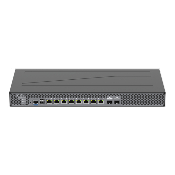
Console port, one GE RJ45 management port, one RJ45 WAN port, and eight GE RJ45 ports. Front and Back Panels The RG-WALL1600-S3200's front and back panels are shown in Figure 1-1. See the description for the detailed parts specified by the numbers in the figure. - Page 5 Note: 1. USB port 4. GE RJ45 WAN port 2. Console port 5. GE RJ45 Ethernet ports 3. GE RJ45 management port...
-
Page 6: Preparation Before Installation
2.1.4 Static Discharge Damage Prevention Although much has been done in RG-WALL1600-S3200 to prevent static electricity, great damage may be caused to the circuitry and equipment when the static electricity exceeds a certain limit. In the communication network of the RG-WALL1600-S3200, electrostatic induction may come from the following sources: External electric field produced by the high-voltage supply cable, lightning, etc;... - Page 7 Make sure that the device is properly grounded when the anti-static wrist strap is connected to the ground through the chassis jack. 2.2 Installation Site Requirements RG-WALL1600-S3200 must be used in the room. To ensure normal operation and a prolonged use life of the equipment, the installation site must meet the following requirements. 2.2.1 Rack Mounting Requirements To mount the RG-WALL1600-S3200 in a cabinet, verify that the cabinet meets the following conditions: ...
- Page 8 2.2.6 System Grounding Requirements A good grounding system is the basis for the stable and reliable operation of the RG-WALL1600-S3200. It is the key to prevent lightning stroke and resist interference. Please carefully check the grounding conditions on the installation site according to the grounding requirements, and perform grounding properly as needed.
- Page 9 Air-laid paper, fiber end microscope Meter Multimeter, Errormeter, Optic-power meter RG-WALL1600-S3200 is not shipped with a tool kit. The tool kit is customer-supplied. 2.5 Unpacking Requirements Goods Checklist Two mounting brackets, USB cables, Ethernet cables, two power cables, Console cables, eight Installation Kit screws, four rubber pads, two SFP transceivers and optical disk containing tools and documents.
-
Page 10: Product Installation
3.1 Installation Procedure 3.2 Installation Verification The RG-WALL1600-S3200 is complicated equipment, so you must carefully plan and arrange the installation location, networking mode, power supply, and wiring before installation. Verify the following before installation: The installation location is of a good air flow. - Page 11 Note that the space between neighboring standard installation holes is a little smaller than that between an auxiliary installation hole and its neighboring standard installation hole. When installing a guide rail for the RG-WALL1600-S3200 series, ensure that the plane to carry the chassis should be installed on the plane of delimiters (entire-U delimiter) of the two neighboring RUs, as shown in Figure 3-1.
- Page 12 Levelly lift the RG-WALL1600-S3200 by two people on both sides, and slowly move it to the front of the cabinet. Levelly lift the RG-WALL1600-S3200 to a position slightly higher than the tray or the slide rail of the cabinet, put the equipment onto the tray or the slide rail, and push it into the cabinet.
- Page 13 Insert the single-mode or multi-mode fiber into the appropriate port according to the identification on the panel of the linecard. Distinguish the Rx/Tx end of the fiber. Insert the twisted pair with the RJ45 port into the appropriate port according to the identification on the panel of the linecard.
-
Page 14: System Debugging
4 System Debugging 4.1 Establishing the Configuration Environment Establishing the Configuration Environment Connect the PC to the console port of the device through the Console cable. Connecting the Console Cable Connect one end of the DB-9 serial connector of the console cable to the serial port of the PC. Connect one end of the Console cable to the Console port of the device. - Page 15 After selecting the serial port, click OK. The Serial Port Parameter Setting window is displayed, as shown in Figure 4-3. Set the baud rate to 9600, data bit to 8, parity check to none, stop bit to 1, and no flow control. Figure 4-3 After setting the serial port parameters, click OK.
- Page 16 Step 3. Set terminal parameters. The parameters are as follows: baud rate 9600, data bit 8, parity check none, stop bit 1, and no flow control. Choose File > Connect, click New Session in the displayed list, and select Serial in the Protocol dropdown list. Click Next, and the following interface will be displayed.
- Page 17 After configuring the parameters, click Next, and you can configure the session name. Click OK, and the following interface will be displayed. Figure 4-7 Click Finish, and the following interface will be displayed. Figure 4-8 4.2 Power-on Startup Checking Before Power-on ...
- Page 18 The console cable is correctly connected; the terminal (can be a PC) used for configuration is already started; the parameters are already configured. Checking After Power-on (Recommended) After power-on, you are recommended to perform the following checks to ensure the normal operation of follow-up configurations.
-
Page 19: Troubleshooting
[Fault Description] The login password is forgotten or lost, and so it is not possible to configure the data. [Troubleshooting] Please contact Ruijie technical support. Fault 2 The AC power module does not work. [Fault Description] The Status LED of each line card is OFF, the Power LED is OFF, and the fan does not work. - Page 20 Check whether the settings of the serial port on the super terminal are the same as the settings above. If not, modify the serial port configuration parameters. If there is still no information output, please contact Ruijie technical support. Fault 4 Illegible characters are displayed on the console.
-
Page 21: Appendix A Connectors And Connection Media
6 Appendix A Connectors and Connection Media 1.1000BASE-T/100BASE-TX/10BASE-T Port 1000BASE-T/100BASE-TX/10BASE-T is a port that supports adaptation of three rates, and automatic MDI/MDIX Crossover at these three rates. The 1000BASE-T complies with IEEE 802.3ab, and uses up to 100m of 100-ohm Category-5 or Supper Category-5 UTP or STP cable. -
Page 22: Appendix B Cabling Recommendations In Installation
7 Appendix B Cabling Recommendations in Installation When RG-WALL1600-S3200 is installed in standard 19-inch cabinets, the cables are tied in the binding rack on the cabinet by the cabling rack, and top cabling or bottom cabling is adopted according to the actual situation in the equipment room. - Page 23 Figure B-2 Bundling up cables (2) When cables need to bend, you should first bundle them up. However, the buckle cannot be bundled within the bend area. Otherwise, significant stress may be generated in cables, breaking cable cores. As shown in Figure B-3. Figure B-3 Bundling up cables (3) ...
- Page 24 The hard power cable should be fastened by the terminal connection area to prevent stress. Do not use self-tapping screws to fasten terminals. Power cables of the same type and in the same cabling direction should be bundled up into cable bunches, with cables in cable bunches clean and straight.
Need help?
Do you have a question about the RG-WALL1600-S3200 and is the answer not in the manual?
Questions and answers