
Related Manuals for J-Tech Digital JTD-2996


Summary of Contents for J-Tech Digital JTD-2996
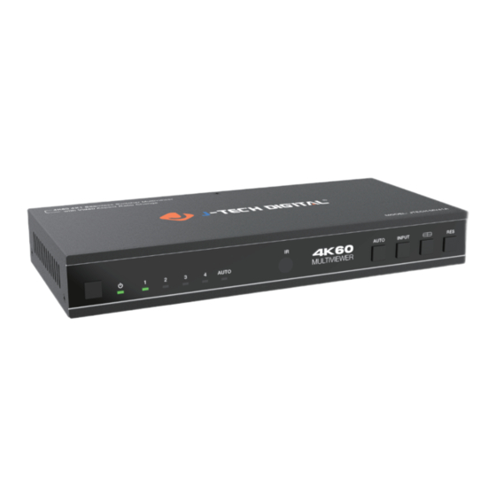
- Page 1 USER MANUAL 4K60 4X1 Seamless Switcher Multiviewer with Video Aspect Ratio Change JTD-2996 I JTECH-MV41A J-TECH DIGITAL INC. 9807 EMILY LANE STAFFORD, TX 77477 TEL: 1-888-610-2818 E-MAIL: SUPPORT@JTECHDIGITAL.COM...
-
Page 2: Table Of Contents
Table of Contents 1. Introduction............................2. Features..............................3. Package Contents..........................4. Specifications............................5. Operation Controls and Functions....................5.1 Front Panel............................5.2 Rear Panel............................5.3 IR Pin Definition..........................6. IR Remote............................... 7. EDID Settings............................8. Video & Audio............................9. Multiview..............................10. OSD Menu Navigation........................11. -
Page 3: Introduction
1. Introduction This 4K60 4x1 Multiviewer Seamless UHD Video Switcher was developed for the purpose of supporting higher output resolution (4K@60) for multiple sources on a single screen. It can combine up to four video signals onto a single UHD or HD displayer. The user can manage each input, and create combinations of the four inputs on a single display, as well as adjust the position of any input. -
Page 4: Package Contents
3. Package Contents 1 x 4K60 4x1 Multiviewer Seamless UHD Video Switcher • 1 x IR Remote • 1 x 3pin-3.81mm Phoenix Connector (male) • 1 x 38KHz IR Wideband Receiver Cable (1.5 meters) • 2 x Mounting Ears • 4 x Machine Screws (KM3*4) •... -
Page 5: Operation Controls And Functions
Connection Input ports 4 x HDMI IN [Type A, 19-pin female] 1 x HDMI OUT [Type A, 19-pin female] Output ports 1 x L/R OUTPUT [RCA] 1 x OPTICAL OUTPUT [S/PDIF] 1 x RS-232 [3pin-3.81mm phoenix connector] Control ports 1 x IR EXT [3.5mm Stereo Mini-jack] Mechanical Housing Metal Enclosure... - Page 6 Name Function Description Input signal indicator lights. In single screen display mode, when the HDMI OUTPUT port Input 1-4 LEDs outputs the signal from the HD 1/2/3/4 port, the corresponding green LED will be on. In multiview mode, all input signal LEDs will light in green. When the device is in the AUTO mode, the AUTO LED will light in green, and HDMI is automatically identified, that is, when the AUTO LED...
-
Page 7: Rear Panel
5.2 Rear Panel OUTPUT INPUT OPTICAL HDMI HD 1 HD 2 HD 3 HD 4 RS-232 IR EXT DC 12V Name Function Description PCM2.0 Analog audio output port. L/R port Optical fiber digital audio output port. OPTICAL port HDMI signal output port, connected to HDMI display device HDMI OUTPUT such as TV or Monitor with HDMI cable. -
Page 8: Ir Remote
6. IR Remote ① Power on or Standby: Press this button to power on the switcher or set it to standby mode. ② HD 1/2/3/4: Press these buttons to select input source in single screen display mode, and the corresponding input LED on the front panel will light in green, and the corresponding input source will be displayed on the OSD of the window. -
Page 9: Edid Settings
7. EDID Settings User can select following EDID modes via RS-232 command, OSD menu navigation or Controller software. No. EDID Mode No. EDID Mode 1680x1050-2.0CH 4K60-2.0CH 1600x1200-2.0CH 4K60-5.1CH 4K60-7.1CH 1440x900-2.0CH 4K30-2.0CH 1360x768-2.0CH 4K30-5.1CH 1280x1024-2.0CH 4K30-7.1CH 1024x768-2.0CH 1080P-2.0CH 720P-2.0CH 1080P-5.1CH AUTO 1080P-7.1CH USER1 1920x1200-2.0CH... -
Page 10: Multiview
9. Multiview The switcher supports 8 categories of multiview display modes: SINGLE, PIP, PBP (1), PBP (2), Triple (1), Triple (2), Quad (1), Quad (2) Users can select different operations for different multiview modes as following: SINGLE: Inputs selection PIP: Inputs selection, Sub window size and position selection PBP (1), PBP (2), Triple (1), Triple (2), Quad (1), Quad (2): Inputs selection, Display mode selection, Display aspect selection Multiview window distributions are as following:... - Page 11 BLACKSCREEN, BLACKSCREEN BLUESCREEN Output ON, OFF Single Input select HDMI1,HDMI2,HDMI3,HDMI4 HDMI1,HDMI2,HDMI3,HDMI4 Win1 Select HDMI1,HDMI2,HDMI3,HDMI4 Win2 Select Right Bottom,Right Top, PIP Position Left Bottom,Left Top Small,Middle,Large PIP Size HDMI1,HDMI2,HDMI3,HDMI4 Win1 Select HDMI1,HDMI2,HDMI3,HDMI4 Win2 Select 1, 2 MODE Aspect Full, 16:9 Multiview HDMI1,HDMI2,HDMI3,HDMI4 Win1 Select HDMI1,HDMI2,HDMI3,HDMI4...
- Page 12 HDMI1,HDMI2,HDMI3, Audio Select HDMI1 HDMI4 AUDIO Volume 0..100 AUDIO-MUTE ON, OFF Language/语言 English English, 中文 4K60-2.0,4K60-5.1CH, 4K60-7.1CH,4K30-2.0CH, 4K30-5.1CH,4K30-7.1CH, 1080P-2.0CH,1080P-5.1CH, 1080P-7.1CH,1920x1200- EDID 4K60-2.0 2.0CH,1680x1050-2.0CH, 1600x1200-2.0CH,1440x900 System -2.0CH, 1360x768-2.0CH, 1280x1024-2.0CH, 1024x 768-2.0CH,720P-2.0CH, AUTO, USER1 115200,57600,38400, Baud rate 115200 19200,9600 Reset Reset Reset FW Version Read only (2) A total of four buttons on the IR Remote are used for audio setting on OSD menu...
-
Page 13: Controller Software Operation Guide
11. Controller Software Operation Guide 11.1 Installation & Connection Follow the steps below to install the Controller software. Step 1. Double-click the following driver to install the Controller software. Step 2. Select “Anyone who uses this computer (all users)”, and then click “Next”. Step 3. - Page 14 Follow the steps below to connect the Controller software and the device. Step 1. Connect the RS-232 port of the switcher to a PC with an RS-232 serial cable and an USB to RS-232 serial cable, as shown in the figure below. Ground 3-pin Phoenix connector RS-232...
-
Page 15: Controller Main Interface
11.2 Controller Main Interface ■ General Page You can do the following operations on the General page: ① Control Mode Select: Select the “COM Control Mode”. (TCP/IP control is not supported temporarily, so the TCP/IP Control Mode is disabled.) ② COM Control Mode: Select the Port number and Baud Rate of the device. ③... - Page 16 ■ Output Page You can do the following operations on the Output page: ① Multi-View Adjustment: Click to select the desired screen display mode. There are eight modes available: SINGLE-PIP-PBP(1)-PBP(2)-Triple(1)-Triple(2)-Quad(1)-Quad(2). ② PIP Adjustment: In the PIP mode, you can switch the location and size of the PIP and set the user-defined PIP, as shown in the following table.
- Page 17 ⑤ Aspect: Click “Full Screen” or “16:9” to switch the display aspect. Only the following modes are available: PBP(1)-PBP(2)-Triple(1)-Triple(2)-Quad(2). ⑥ Auto Switch: Enable or disable the function of automatically switching input signal source, available only in SINGLE mode. ⑦ Output Setting: Set the output resolution, video keep alive, PC/Video PQ, HDCP, audio source and audio output.
-
Page 18: Rs-232 Command
12. RS-232 Command The product also supports RS-232 command control. Connect the RS-232 port of the product to a PC with an RS-232 to USB serial cable. Then open a Serial Command tool on PC to send ASCII commands to control the product. The ASCII command list about the product is shown as below. - Page 19 Command Code Default Function Description Example Feedback Output Setting Set Output Resolution (x=1~15) 1. 4096x2160p60, 2. 4096x2160p50, 3. 3840x2160p60, 4. 3840x2160p50, 5. 3840x2160p30, 6. 3840x2160p25, out resolution: 7. 1920x1200p60RB, 3840x2160p s output res x! s output res 3! 8. 1920x1080p60, 3840x2160p60 9.
- Page 20 Command Code Function Description Example Feedback Default EDID Setting Set HDMI input EDID mode (x=1~19) 1. 4K2K60_444,Stereo Audio 2.0 2. 4K2K60_444,Dolby/DTS 5.1 3. 4K2K60_444,HD Audio 7.1 4. 4K2K30_444,Stereo Audio 2.0 5. 4K2K30_444,Dolby/DTS 5.1 6. 4K2K30_444,HD Audio 7.1 7. 1080P,Stereo Audio 2.0 input EDID:4K2K 4K2K60_ 8.
- Page 21 Command Code Function Description Example Feedback Default r output audio r output audio output audio Get output audio volume vol! vol! volume: 30 Set output audio mute on/off (x=0~1) s output audio s output audio output audio mute: 0. mute off mute x! mute 0! 1.
- Page 22 Command Code Default Function Description Example Feedback Get windows selected input source (x=0~4) 0. ALL window 1 select r window x in! r window 1 in! 1. window 1 HDMI 1 2. window 2 3. window 3 4. window 4 Set the border mode of the specified window.
- Page 23 Command Code Function Description Example Feedback Default Set PIP window to user define mode Hstart=(1~100) s PIP Hstart s PIP 10 10 20 Vstart=(1~100) PIP 10 10 20 20 Vstart Hsize Hsize=(1~100) Vsize! Vsize=(1~100) NOTE:Hstart+Hsize<=101, Vstart+Vsize<=101 Set PIP window position (x=1~5) 1.
- Page 24 Command Code Function Description Example Feedback Default r triple mode! r triple mode! Get triple windows display mode triple mode 1 Set triple windows display triple aspect: triple aspect: aspect ratio (x=1~2) s triple aspect 1! s triple aspect x! full screen full screen 1.
-
Page 25: Application Example
13. Application Example UHDTV OUTPUT INPUT OPTICAL HDMI HD 1 HD 2 HD 3 HD 4 RS-232 IR EXT DC 12V Power Supply Audio Amplifier IR Receiver 2.0 Speakers TV box DVD or Blu-ray Player... -
Page 26: Maintenance
14. Maintenance Clean this unit with a soft, dry cloth. Never use alcohol, paint thinner, or benzine to clean. 15. Warranty If your product does not work properly because of a defect in materials of workmanship, our company (referred to as “the warrantor”) will, for the length of the period indicated as below, “Parts and Labor (18) Months”, which starts with the date of original purchase (“Limited Warranty period”), at its option either (a) repair your product with new or refurbished parts, or (b) replace it with a new or a refurbished product. -
Page 27: Limited Warranty Limits And Exclusions
17. Limited Warranty Limits and Exclusions This Limited Warranty ONLY COVERS failures due to defects in material or workmanship, and DOES NOT COVER normal wear and tear or cosmetic damage. The Limited Warranty ALSO DOES NOT COVER damages which occurred in shipment, or failures which are caused by products not supplied by warrantor, or failures which result from accidents, misuse, abuse, neglect, mishandling, misapplication, alteration, faulty installation, set-up adjustments, mis-adjustment of consumer controls, improper... - Page 28 WWW.JTECHDIGITAL.COM PUBLISHED BY J-TECH DIGITAL INC. 9807 EMILY LANE STAFFORD, TX 77477 TEL: 1-888-610-2818 E-MAIL: SUPPORT@JTECHDIGITAL.COM...
Need help?
Do you have a question about the JTD-2996 and is the answer not in the manual?
Questions and answers