
Related Manuals for J-Tech Digital JTD-2886


Summary of Contents for J-Tech Digital JTD-2886
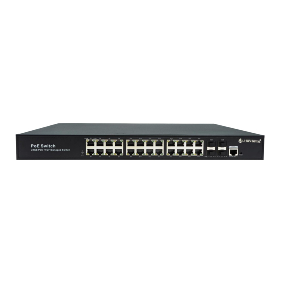
- Page 1 USER MANUAL 24 PORT POE SWITCH JTD-2886 | JTECH-NSP24 48 PORT POE SWITCH JTD-2887 | JTECH-NSP48 J-TECH DIGITAL INC. 9807 EMILY LANE STAFFORD, TX 77477 TEL: 1-888-610-2818 E-MAIL: SUPPORT@JTECHDIGITAL.COM...
-
Page 2: Table Of Contents
Table of Contents: 1. Introduction.......................6 1.1 Product Introduction......................6 1.2 Features ..........................6 1.3 Overview ..........................7 1.4 Web Management ......................7 1.5 Web-based User Interface ....................8 1.6 Main Menu ........................9 2. Network Management ..................10 2.1 IP Configuration ......................10 2.2 NTP Configuration ......................11 2.3 Time Zone ........................12 2.4 SNMP Configuration......................13 2.4.1 SNMP System Configuration ....................14... - Page 3 3.2.2 LACP Aggregation ........................24 3.3 Port Mirroring .........................25 3.4 Thermal Protection Configuration ................26 4. PoE Configuration ....................27 4.1 PoE Setting ........................29 4.2 PoE Status ........................30 4.3 PoE Scheduling ......................30 5. Advanced Configuration ..................31 5.1 VLAN ..........................31 5.2 Port Isolation ........................35 5.2.1 Port Group ..........................35 5.2.2 Port Isolation ..........................36 5.3 STP ..........................36...
- Page 4 5.7.1 Basic Configuration .........................48 5.7.2 VLAN Configuration ........................49 5.8 ERPS ..........................49 5.9 LLDP ..........................52 5.10 Loop Protection ......................53 6. QoS Configuration ....................54 6.1 QoS Port Classification ....................54 6.2 Port Policing ........................55 6.3 Storm Control Configuration ..................56 7. Security Configuration ..................57 7.1 Password.........................57 7.2 802.1X ..........................57 7.3 DHCP Snooping ......................59...
- Page 5 7.6.2 Rate Limiter Configuration ....................68 7.6.3 Access Control List Configuration ..................69 8. Diagnostics ......................70 8.1 Ping Test .........................70 8.2 Cable Diagnostics ......................71 8.3 CPU Load ........................71 9. System Defaults ....................72 9.1 Restart Device ........................72 9.2 Factory Default ......................72 9.3 Firmware Upgrade ......................73 9.4 Firmware Select ......................73 9.4.1 Download Configuration File ....................74 9.4.2 Upload Configuration File ......................75...
-
Page 6: Introduction
1. Introduction 1.1 Product Introduction This series supports IPv4 / IPv6 double stack platform, and supports a variety of senior management functions, including POE management, MAC Table, VLANs, Port Isolation, Loop Protection, IGMP Snooping, MLD Snooping, ERPS, DHCP client, DHCP Snooping, STP/RSTP/MSTP, 802.1 x, QoS, port mirror, LLDP, static routing and NTP etc., 128 static routing and basic QINQ, to provide users with the perfect solution;... -
Page 7: Overview
• Port mirror, convenient for online debug • Cable testing, convenient for the examining cable length in a project • STP/RSTP/MSTP, enhance the stability of network • IEEE802.1Q VLAN, IEEE802.1ad QINQ • 802.1x authentication to port and MAC • Static routing L3 switching technology •... -
Page 8: Web-Based User Interface
Default User Name: admin Default Password: system 1.5 Web-based User Interface After entering the username and password, the main screen appears as shown in Figure 1- P a g e... -
Page 9: Main Menu
This Main Page interface includes mainly 3 parts. Here is the description: The Web agent displays an image of the Managed Switch’s ports. Different colors mean different states, they are illustrated as follows: 1.6 Main Menu Using the onboard Web agent, you can define system parameters, manage and control the Managed Switch, and all its ports, or monitor network conditions. -
Page 10: Network Management
2. Network Management 2.1 IP Configuration Note: IP address of switch is 192.168.2.1 by default, and the default subnet mask is 255.255.255.0 (24). Click "Network Admin" > ''IP'', and the screen will show as: 10 | P a g e... -
Page 11: Ntp Configuration
Following is description detail about IP configuration: Click ''Add Interface'' to create a new management for VLAN and IP address. Click ''Save'' to save settings. Note: The switch only created VLAN1 by default. If user needs to use other VLAN for switch management, please first add VLAN in the VLAN module, and add the relevant port to the VLAN. -
Page 12: Time Zone
Configuration object and description is: After configuration was set, please click "Save" to save the setting. 2.3 Time zone Time zone is to set the time of the switch, users can set the time according to their locations. You can get into the time zone through “Network admin” > “Time zone”, as below figure 2-3. -
Page 13: Snmp Configuration
2.4 SNMP Configuration Simple Network Management Protocol (SNMP) is an application layer protocol that facilitates the exchange of management information between network devices. It is part of the Transmission Control Protocol/Internet Protocol (TCP/IP) protocol suite. SNMP enables network administrators to manage network performance, find and solve network problems, and plan for network growth. -
Page 14: Snmp System Configuration
Trap Used by the agent to asynchronously inform the NMS of some event. These events may be very serious, such as reboot (someone accidentally turned off switch), or just general information, such as port status change. In these cases, switch create trap information and send then to receiver or network admin. -
Page 15: Snmp Trap Configuration
Configuration object and description is: 2.4.2 SNMP Trap Configuration User can enable or disable SNMP Trap function and set configuration. Click "Network Admin" > "SNMP" > "Trap", then this screen will show as: 15 | P a g e... -
Page 16: Communities
2.4.3 Communities Users can set the new community’s name through “Network admin” > “SNMP” > “Communities”, as below figure 2-4-3. Figure 2-4-3 Adding Community Configuration Instruction: 2.4.4 Users SNMP v3 is using USM (User-Based Security Model) authentication mechanism. The administrator can set authentication and Encryption function. The authentication is to verify the validity of a message sender and to avoid illegal user access. -
Page 17: Views
Configuration Instruction: 2.4.5 Views Users can set the visit view of SNMPv3. Click “Network Admin” > “SNMP” > “View”. As below: 17 | P a g e... -
Page 18: Access
2.4.6 Access Uses can set an Access to load a built Views. Click “Network Admin” > “SNMP” > “Access”, as below: Figure 2-4-6 SNMPv3 Access Load Set 18 | P a g e... -
Page 19: Groups
2.4.7 Groups Users can set Groups to load built Users and Access. Click “Network Admin” > “SNMP” > “Groups”, as below: Figure 2-4-7 SNMPV3 Groups Load Setting 19 | P a g e... -
Page 20: System Log Configuration
Configuration Instruction: 2.5 System Log Configuration Users can configure switch’s system log, via following screen after clicking "Network Admin" > "Syslog”. Configuration object and description is: 20 | P a g e... -
Page 21: Port Configuration
3. Port Configuration 3.1 Port Configuration This page is for configuring port specifications of switch. After clicking "Port Configure" > "Ports", this screen will appear as: 21 | P a g e... -
Page 22: Link Aggregation
Configuration object and description is: Click "Save" to store and active settings. 3.2 Link Aggregation Users can set up multiple links among multiple switches. Link Aggregation, is a method that tie some physical ports together as one logic port, to enlarge bandwidth. This switch supports up to 13 groups Link Aggregation, 2 to 8 ports as one group. - Page 23 Configuration object and description is: Click "Save" to store and active settings. Note: It allows a maximum of 8 ports to be aggregated as 1 static trunk group at the same time. 23 | P a g e...
-
Page 24: Lacp Aggregation
3.2.2 LACP Aggregation Link Aggregation Control Protocol (LACP) provides a standardized means for exchanging information between Partner Systems that require high-speed redundant links. Link aggregation lets you group up to eight consecutive ports into a single dedicated connection. This feature can expand bandwidth to a device on the network. LACP operation requires full-duplex mode. -
Page 25: Port Mirroring
Configuration object and description is: Click "Save" to store and active settings. 3.3 Port Mirroring Configure port Mirroring on this page. This function provides monitoring of network traffic that forwards a copy of each incoming or outgoing packet from one port of a network switch to another port where the packet can be studied. -
Page 26: Thermal Protection Configuration
Figure 3-4 Mirror Configuration Screen Configuration object and description is: Note: You cannot set fast speed port(s) mirror to a low-speed port. For example, there is problem if you try to mirror 100Mbps port(s) to a 10 Mbps port. So, destination port should have equal or higher speed comparing to source port. -
Page 27: Poe Configuration
Configuration object and description is: Note: By default, all ports of switch belong to Priority Group 0, with protected temperature 225-degree C. 4. PoE Configuration Power-over-Ethernet (PoE), means Ethernet network power supply via 100BASE-TX, 1000BASE-T. Its maximum power distance is 100 meters. By PoE power system, based on Ethernet wiring network of UTP Cat5 or higher Cable, it can give power to IP camera, VoIP phone, wireless AP, as well as transmit data. - Page 28 PoE power supply system has unified standard, IEEE 802.3af and 802.3at. So, devices from different manufacturers have no problem in general usage, as long as they are complied with these standards. PD, it is defined as powered device in the PoE Power Supply System, primarily including IP camera, wireless AP, network VoIP phone, and other IP-based terminal equipment.
-
Page 29: Poe Setting
4.1 PoE Setting After clicking "PoE" > "PoE Setting", user can make PoE settings in following screen: Configuration object and description is: 29 | P a g e... -
Page 30: Poe Status
4.2 PoE Status In this page, user can check and look PoE status of all ports, after clicking "PoE" > "PoE Status". 4.3 PoE Scheduling This series supports PoE scheduling, users can set timing PoE reboot and enable/disable PoE on time schedule. Click “PoE”... -
Page 31: Advanced Configuration
5. Advanced Configuration 5.1 VLAN VLAN (Virtual Local Area Network) logically divide one LAN (Local Area Network) into a plurality of subsets, and each subset will form their own broadcast area network. In short, VLAN is a communication technology that logically divide one physical LAN into multiple broadcast area network (multiple VLAN). - Page 32 Configuration object and description is: 32 | P a g e...
- Page 33 33 | P a g e...
- Page 34 34 | P a g e...
-
Page 35: Port Isolation
5.2 Port Isolation Port isolation is for limiting data between ports. It is similar to VLAN, but stricter. 5.2.1 Port Group This switch support port groups. Members of port group can forward date. Note: port can belong to multiple port groups. Data can be forwarded among any port that belong to one port group. -
Page 36: Port Isolation
Click "Add New Port Group" to create a new port group, "Delete" to remove corresponding port group, and "Save" to store and active settings. 5.2.2 Port Isolation After clicking "Advanced Configure" > "Port Isolation">"Port Isolation", then following screen will appear for making port isolation configuration: Configuration object and description is: Click "Save"... - Page 37 Configuration object and description is: 37 | P a g e...
-
Page 38: Msti Mapping
Click "Save" to store and active settings. 5.3.2 MSTI Mapping Users can set the mapping. Click “Advanced Configure” > “Spanning Tree” > “MSTI Mapping”. Configuration Instruction: 38 | P a g e... -
Page 39: Msti Priorities
Note: Please set the same value for configuration name and configuration revision of all switches in the looped network when set MSTP. 5.3.3 MSTI Priorities Users can set MSTI priorities, click “advanced configure” > “Spanning Tree” > “MSTI Priorities” Note: The priority value must be in multiples of 4094, at the range of 0-6144 39 | P a g e... -
Page 40: Stp Bridge Port
5.3.4 STP Bridge Port After clicking "Advanced Configure" > "Spanning Tree" > "Bridge Ports", following screen will appear: Configuration object and description is: 40 | P a g e... -
Page 41: Msti Ports
Click "Save" to store and active setting. 5.3.5 MSTI Ports Users can set MSTI ports, click “Advanced Configure” > “Spanning Tree” > “MSTI Ports” Configuration Instruction: 41 | P a g e... -
Page 42: Mac Address Table
5.4 MAC Address Table This page allows you to configure Mac address table settings. After clicking "Advanced Configure" > "Mac Table", following screen will appear. Configuration object and description is: 42 | P a g e... -
Page 43: Igmp Snooping
5.5 IGMP Snooping Internet Group Management Protocol (IGMP) lets host and routers share information about multicast groups memberships. IGMP snooping is a switch feature that monitors the exchange of IGMP messages and copies them to the CPU for feature processing. The overall purpose of IGMP Snooping is to limit the forwarding of multicast frames to only ports that are a member of the multicast group. -
Page 44: Igmp Snooping Vlan Configuration
Configuration object and description is: 5.5.2 IGMP Snooping VLAN Configuration After clicking "Advanced Configure" > "IGMP Snooping" > "VLAN Configuration", following screen will appear: Configuration object and description is: 44 | P a g e... -
Page 45: Port Filtering Profile
5.5.3 Port Filtering Profile Set Port filtering profile, click “Advanced Configure” > “IGMP Snooping” > “Port Filtering Profile” 45 | P a g e... -
Page 46: Ipmc Profile
Configuration Instruction: 5.6 IPMC Profile Users can set the filter multicast list, click “Advanced Configure” > “IPMC Profile” > “Address Entry” Configuration Instruction: Click “Save” to enable your setting Bind the filter multicast list, click “Advanced Configure” > “IPMC Profile” > “Profile Table 46 | P a g e... -
Page 47: Ipv6 Mld Snooping
Figure 5-6 IGMP Snooping Setting 5.7 IPV6 MLD Snooping IPV6 MLD Snooping is a multicast management and control mechanism working on the Layer 2 Ethernet switch When enable IPV6 MLD Snooping, switch receives the IPV6 MLD message by listening for each interface, to exchange interface and multicast group address mapping relationship, and according to establish the mapping relationship to forward the multicast data flow. -
Page 48: Basic Configuration
5.7.1 Basic Configuration Click “Advanced Configure” > “IPv6 MLD Snooping” > “Basic Configuration”, to check the configuration information of IPv6 MLD Snooping. Configuration Instruction: 48 | P a g e... -
Page 49: Vlan Configuration
Click “Save” to enable your setting. 5.7.2 VLAN Configuration Click “Advanced Configure” > “IPv6 MLD Snooping” > “VLAN Configuration”, to check configuration information of IPv6 MLD Snooping. Configuration Instruction: 5.8 ERPS ERPS (Ethernet Ring Protection Switching), it integrates OAM function and APS protocol. If the ring network was interrupted accidentally, the fault recovery times could be less than 50ms to quickly bring the network back to normal operation. - Page 50 industry standard for ERPS. Note: Before enable ERPS, STP of ring port should be disabled. After clicking "Advanced Configure" > "ERPS ", following screen will appear: Configuration object and description is: Click "Add New Ring Group "to create a new ERPS ring application. Click "Save"...
- Page 51 After clicking the number under "Ring ID", it will go to the page for Ring Configuration as following screen: Configuration object and description is: After clicking ''VLAN config'', it will go the page of Rapid Ring VLAN Configuration as following screen: 51 | P a g e...
-
Page 52: Lldp
Click "Add New Entry" to create a new entry. Click "Save" to store and active settings. 5.9 LLDP Link Layer Discovery Protocol (LLDP) is used to discover basic information about neighboring devices on the local broadcast domain. LLDP is a Layer 2 protocol that uses periodic broadcasts to advertise information about the sending device. -
Page 53: Loop Protection
Configuration object and description is: 5.10 Loop Protection Loop protection is to avoid broadcast loops. After clicking "Advanced Configure" > "Loop Protection", following screen will appear: Configuration object and description is: 53 | P a g e... -
Page 54: Qos Configuration
6. QoS Configuration Quality of Service (QoS) is an advanced traffic prioritization feature that allows you to establish control over network traffic. QoS enables you to assign various grades of network service to different types of traffic, such as multi-media, video, protocol-specific, time critical, and file-backup traffic. -
Page 55: Port Policing
Configuration object and description is: 6.2 Port Policing After clicking "QoS Configure" > "Port Policing", following screen will appear: 55 | P a g e... -
Page 56: Storm Control Configuration
Configuration object and description is: 6.3 Storm Control Configuration After clicking "QoS Configure" > "Storm Control", following screen will appear: 56 | P a g e... -
Page 57: Security Configuration
Configuration object and description is: 7. Security Configuration 7.1 Password To change system login password of the switch, please click "Security Configure" > "Password”. Figure 7-1 System Password Configuration Screen Click "Save" to store and active settings. 7.2 802.1X In the 802.1X-world, the user is called the supplicant, the switch is the authenticator, and the RADIUS server is the authentication server. - Page 58 Frames sent between the supplicant and the switch are special 802.1X frames, known as EAPOL (EAP over LANs) frames. EAPOL frames encapsulate EAP PDUs (RFC3748). Frames sent between the switch and the RADIUS server are RADIUS packets. RADIUS packets also encapsulate EAP PDUs together with other attributes like the switch's IP address, name, and the supplicant's port number on the switch.
-
Page 59: Dhcp Snooping
Configuration object and description is: 7.3 DHCP Snooping 7.3.1 DHCP Overview DHCP protocol is widely used to dynamically allocate reusable network resources, such as IP address. Typical process of DHCP to obtain IP is as following: DHCP Client sent DHCP DISCOVER message to DHCP Server, if Client did not receive respond from server within a period of time, it will resend DHCP DISCOVER message. -
Page 60: About Dhcp Snooping
DHCP ACK message, start using the source which server assigned. If received DHCP NAK, DHCP Client will resend DHCP DISCOVER message. 7.3.2 About DHCP Snooping The addresses assigned to DHCP clients on insecure ports can be carefully controlled using the dynamic bindings registered with DHCP Snooping. DHCP snooping allows a switch to protect a network from rogue DHCP servers or other devices which send port-related information to a DHCP server. -
Page 61: Dhcp Snooping Configuration
7.3.3 DHCP Snooping Configuration After clicking ''Security Configure'' > ''DHCP” > ''Snooping Setting'', following screen will appear: Configuration object and description is: Click "Save" to store and active settings. 7.4 IP & MAC Source Guard IP & MAC Source Guard is a secure feature used to restrict IP traffic on DHCP snooping 61 | P a g e... -
Page 62: Port Configuration
untrusted ports by filtering traffic based on DHCP Snooping Table or manually configured IP Source Bindings. It helps prevent IP spoofing attacks when a host tries to spoof and use the IP address of another host. 7.4.1 Port Configuration In this page, user can make IP & MAC Source Guard Port Configuration. After clicking ''Security Configure'' >... -
Page 63: Static Table
7.4.2 Static Table In this page, user can manually set Static Table of IP & MAC Guard to fulfill controlling function to port. After clicking ''Security Configure'' > ''IP & MAC Source Guard” > ''Static Table'', followed screen will appear: Configuration object and description is: Click "Save"... -
Page 64: Arp Inspection
7.5 ARP Inspection Dynamic ARP Inspection (DAI) is a secure feature. Several types of attacks can be launched against a host or devices connected to Layer 2 networks by "poisoning" the ARP caches. This feature is used to block such attacks. Only valid ARP requests and responses can go through DUT.A Dynamic ARP prevents the untrust ARP packets based on the DHCP Snooping Database. -
Page 65: Vlan Configuration
7.5.2 VLAN Configuration After clicking ''Security Configure'' > ''ARP Inspection'' > ''VLAN Configuration'', following screen will appear: 65 | P a g e... -
Page 66: Static Table
Configuration object and description is: 7.5.3 Static Table User can manually configure ARP Inspection Static Table to control port. After clicking ''Security Configure'' > ''ARP Inspection'' > ''Static Table'', following screen will appear: Configuration object and description is: 66 | P a g e... -
Page 67: Acl
7.6 ACL ACL is an acronym for Access Control List. It is the list table of ACEs, containing access control entries that specify individual users or groups permitted or denied to specific traffic objects, such as a process or a program. Each accessible traffic object contains an identifier to its ACL. -
Page 68: Rate Limiter Configuration
7.6.2 Rate Limiter Configuration User can make ACL Rate limiter configuration in this page. After clicking ''Security Configure'' > ''ACL'' > ''Rate Limiter'', following screen will appear: 68 | P a g e... -
Page 69: Access Control List Configuration
Click "Save" to store and active settings. 7.6.3 Access Control List Configuration User can make Access Control List Configuration in this page. After clicking ''Security Configure'' > ''ACL'' > ''Access Control List'', following screen will appear: 69 | P a g e... -
Page 70: Diagnostics
8. Diagnostics 8.1 Ping Test Ping is a little program that can issue ICMP Echo packets to the IP address you defined. Destination node will respond to those packets sent from switch. So, Ping test is to troubleshoot IP connectivity issues. After clicking ''Diagnostics '' >... -
Page 71: Cable Diagnostics
8.2 Cable Diagnostics The Cable Diagnostics performs tests on 10/100/1000BASE-Tcopper cables. These functions have the ability to identify the cable length and operating conditions, and to isolate a variety of common faults that can occur on the Cat5 twisted-pair cabling. After clicking ''Diagnostics'' >... -
Page 72: System Defaults
9. System Default 9.1 Restart Device This page is for restarting switch. After clicking ''Maintenance '' > ''Restart Device'', following screen will appear: 9.2 Factory Default This page is for making all settings to factory defaults. After clicking ''Maintenance '' > ''Factory Defaults'', following screen will appear: Please click ''Yes'' to reset the configuration to Factory Defaults. -
Page 73: Firmware Upgrade
9.3 Firmware Upgrade This page is for upgrading system firmware. After clicking ''Maintenance '' > ''Firmware Upgrade'', following screen will appear: Please click ''Browse'' to select the firmware that needed to upgrade. And then click ''Upload'' to start upgrading. 9.4 Firmware Select This page is for upgrading system firmware. -
Page 74: Download Configuration File
Please click ''Activate Alternate Image'' to select the firmware. In this page, user can download, upload, activated or delete configuration files. 9.4.1 Download Configuration File After clicking ''Maintenance '' > ''Download'', following screen will appear: 74 | P a g e... -
Page 75: Upload Configuration File
Please choose a file and then click ''Download Configuration'' button to download. 9.4.2 Upload Configuration File After clicking ''Maintenance '' > ''Upload'', following screen will appear. Then user can upload Configuration File. 75 | P a g e... -
Page 76: Activate Configuration
9.4.3 Activate Configuration After clicking ''Maintenance '' > ''Activate'', following screen will appear. Then user can activate Configuration File. 9.4.4 Delete Configuration File After clicking ''Maintenance '' > ''Delete'', following screen will appear. Then user can delete Configuration File. 76 | P a g e... -
Page 77: Appendix 1 Term List
10. Appendix 1 Term List 77 | P a g e... -
Page 78: Appendix 2 Faq
11. Appendix 2 FAQ 1. Why is it not normal to display a page through a WEB browsing configuration? A: Before accessing the WEB, remove the cache and COOKIES of IE. Otherwise, it may cause the abnormal. 2. Forget the Password? A: Forgetting the login password can be used to initialize the password by restoring the factory settings. -
Page 79: Maintenance
network cables. b. The network cable and switch port remain unchanged and change the computer; c. The network cable and computer remain unchanged and replace the switch ports; d. If confirmed that is caused by the switch port failure, please contact the supplier for maintenance 6. -
Page 80: Mail-In Service
14. Mail-In Service When shipping the unit, carefully pack and send it prepaid, adequately insured, and preferably in the original carton. Include a letter detailing the complaint and provide a day time phone and/or email address where you can be reached. 15. - Page 81 WWW.JTECHDIGITAL.COM PUBLISHED BY J-TECH DIGITAL INC. 9807 EMILY LANE STAFFORD, TX 77477 TEL: 1-888-610-2818 E-MAIL: SUPPORT@JTECHDIGITAL.COM 81 | P a g e...
Need help?
Do you have a question about the JTD-2886 and is the answer not in the manual?
Questions and answers