
Related Manuals for J-Tech Digital JTECH-VWM90


Summary of Contents for J-Tech Digital JTECH-VWM90
- Page 1 USER MANUAL 5 Input | 3x3 video wall w/ rotation JTD-2921 | JTECH-VWM90 J-TECH DIGITAL INC. 9807 EMILY LANE STAFFORD, TX 77477 TEL: 1-888-610-2818 E-MAIL: SUPPORT@JTECHDIGITAL.COM...
-
Page 2: Table Of Contents
Table of Contents 1. Product Overview ..................3 1.1 Product Features ......................3 1.2 Specifications ......................3 2. Operation Instructions ................4 2.1 Product Panel Description ................... 4 2.2 Remote Control Button Guide ..................7 2.3 Remote Control Operation Instructions................ 10 2.4 RS232 Control (Serial Port Instructions) .............. -
Page 3: Product Overview
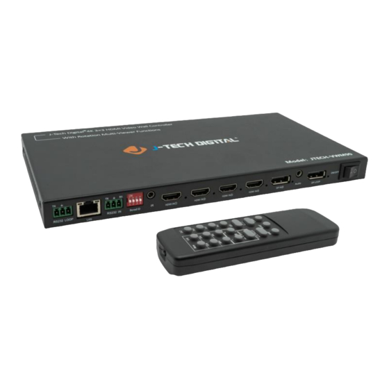
Product Overview Product Features JTECH-VWM90 is an Ultra-HD Rotary Splicer Video Wall controller by J-Tech Digital. It supports 4 HDMI inputs (1 HDMI Port supports 4K@60Hz, 3 HDMI Ports support 4K@30Hz), 1 DP input (4K@60Hz), 9 HDMI outputs (1080P@60Hz), and 1 DP local loop out. There is support for multiple splicing modes, such as horizontal screen, vertical screen, 2x2, and the unit supports large-scale cascading and parallel use in form of loop-out. -
Page 4: Operation Instructions
Audio Output 3.5mm Headphone Control Method Remote Control, RS232 Serial Port (Can be looped out) Factory Default Resolution HDMI: 3840*2160@60Hz DP: 3840*2160@60Hz Custom Resolution Support Default IP Address 192.168.1.192 Default WebGUI Password admin1 Operating Temperature 0°C – 50°C | 32°F – 122°F Power Consumption Power Supply 12V@2A AC-DC... - Page 5 K. 3.5mm Audio out interface for external audio devices L. DP local loop-out. When multiple devices are cascaded, this port acts as the DP input source for other JTECH-VWM90 devices. The LED light next to this interface indicates that there is a loop-out signal output (In single screen mode, the loop-out follows the selection of the input source channel to switch.
- Page 6 Note 1: DIP switch, when cascading, will indicated the ID number of the current device which is set in binary. P a g e...
-
Page 7: Remote Control Button Guide
2.2 Remote Control Button Guide P a g e... - Page 8 Confirm Key Escape Key Set Splicing Mode: Row (Range 1-16) Set Splicing Mode: Column (Range 1-16) Window: The number of each screen (window) in “whole screen”. See Note 2 at the end of this table for details Source: Enter the number of the source, 1 for HDMI, 2 for DP Cooperation【...
- Page 9 Note 2: [Win] key meaning: The number of each screen (window) in the “whole screen”, the corresponding position is as follows: Single Screen Mode: There is only one screen, and the value is fixed as number 1, as shown below: Double Picture (PIP Mode): The face value of the large picture is No.1, and the value of the small picture is No.
-
Page 10: Remote Control Operation Instructions
Four Screen Mode: The value of the upper left screen is No. 1. The value of the lower left screen is No.2. The value of the upper right screen is No. 3. The value of the lower right screen is No.4, as shown below: 2.3 Remote Control Operation Instructions The adjustment of the following two groups of parameters needs to press the [Ent] confirmation key to take effect, and the [Esc] cancel key can be pressed when the parameter setting needs to be... -
Page 11: Rs232 Control (Serial Port Instructions)
2.4 RS232 Control (Serial Port Instructions) Parameter Settings: Baud Rate: 9600bps Data Bit: 8 bits Stop Bit: 1 bit Parity: None Function Byte 1 Byte 2 Byte 3 Byte 4 Byte 5 cmd head cmd type cmd_data1 cmd_data2 Check_sum Splicing Mode 0x66 0x01 Byte 1 + Byte 2 + Byte... - Page 12 • [WindowSel]: Window selection, the value depends on the setting of multi-screen mode: [Mode]=0, WindowSel=0 (current screen) [Mode]=1, WindowSel=0 (left picture), WindowSel=1 (right picture) [Mode]=2, WindowSel=0 (upper left screen), WindowSel=1 (lower left screen) WindowSel=2 (upper right screen), WindowSel=3 (lower right screen) [Mode]=3, WindowSel=0 (large picture), WindowSel=1 (small picture) [Mode]=4, WindowSel=0 (upper screen), WindowSel=1 (lower screen) [SourceChannel]: Input source channel selection: 0 is HDM I, 1 is HDMI 2, 2 is HDMI 3,3...
-
Page 13: Product Connection Diagram
Product Connection Diagram 3.1 Instructions for a single unit Taking 3x3 as an example: Front panel wiring diagram The Board ID of the DIP switch on the front panel of the current device needs to be set at: 13 | P a g e... -
Page 14: Instructions For Cascading Two Units
3.2 Instructions for cascading two units Take the output 3x6 image as an example: front panel wiring diagram When cascading, the board ID of the 1 / 2 front panel dial switch of the device needs to be set: 14 | P a g e... -
Page 15: Instructions For Cascading Three Units
Note: When the devices are cascaded, the image rank (MxN rank) must be the same. 3.3 Instructions for cascading three units Take the output of 3x9 as an example: When cascading, the board ID of the 1 / 2 / 3 front panel dial switch of the devices needs to be set: 15 | P a g e... -
Page 16: Definition Of Rows And Columns
3.2 Definition of Rows and Columns Supported Resolutions Note: The support of equal scale mode and resolution is not limited to the following tables. Table 1: Equal proportion mode supported by video card application Mode Full Screen Input Full Screen Output Single Screen Resolution Resolution... - Page 17 1920x5400@60Hz 1920x1080@60Hz 1184x3996@30Hz 1920x6480@60Hz 1920x1080@60Hz 992x3906@30Hz 1280x5040@60Hz 1280x720@60Hz 880x3960@30Hz 1280x5760@60Hz 1280x720@60Hz 784x3969@30Hz 1280x6480@60Hz 1280x720@60Hz Table 2: JTECH-VWM90 Cascade Mode-Supported Resolution Summary Mode Full Screen Input Full Screen Output Single Screen Resolution Resolution Resolution 4080x918@30Hz 6440x1440@60Hz 1280x720@60Hz 4080x765@30Hz 7680x1440@60Hz 1280x720@60Hz 4096x576@30Hz...
-
Page 18: Common Problems
3024x2835@30Hz 3840x3600@60Hz 1280x720@60Hz 3008x2115@30Hz 5120x3600@60Hz 1280x720@60Hz 4080x2295@30Hz 6400x3600@60Hz 1280x720@60Hz 1920x3240@30Hz 2560x4320@60Hz 1280x720@60Hz 2640x2970@30Hz 3840x4320@60Hz 1280x720@60Hz 3072x2592@30Hz 5120x4320@60Hz 1280x720@60Hz 2160x3240@30Hz 3840x5760@60Hz 1280x720@60Hz Common Problems 1. What is the output resolution of the loop-out interface? If the loop-out interface of the first device outputs 3840x2160 resolution, the resolution of the DP input signal of the second device is 3840x2160 resolution. -
Page 19: Appendix
Appendix When the image is not rotated, the output interface is first up and then down, first left and then right. Please refer to the picture below showing 3x9 mode: When the image is rotated 90°, the output interface is first up and then down, first left and then right as shown below in 2x9 example: 19 | P a g e... -
Page 20: Product Service
Product Service 1) Damage requiring service: The unit should be serviced by qualified service personnel if: (a) The DC power supply cord or AC adapter has been damaged; (b) Objects or liquids have gotten into the unit; (c) The unit has been exposed to rain; (d) The unit does not operate normally or exhibits a marked change in performance;... -
Page 21: Limited Warranty Limits And Exclusions
LIMITED WARRANTY, ARE YOUR RESPONSIBILITY. 11. Extended Warranty With the registration of supported J-Tech Digital products, you extend the current warranty by 6 months. This extension is added to the warranty that starts at the purchase date of the device supported. - Page 22 WWW.JTECHDIGITAL.COM PUBLISHED BY J-TECH DIGITAL INC. 9807 EMILY LANE STAFFORD, TX 77477 TEL: 1-888-610-2818 E-MAIL: SUPPORT@JTECHDIGITAL.COM 22 | P a g e...
Need help?
Do you have a question about the JTECH-VWM90 and is the answer not in the manual?
Questions and answers