Advertisement
Quick Links
Advertisement

Related Manuals for J-Tech Digital JTD-793v2


Summary of Contents for J-Tech Digital JTD-793v2
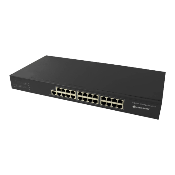
- Page 1 J-Tech Digital 24-Port Switch Matrix JTD-793v2 | JTECH-NS24...
- Page 2 Firmware upgrades and free technical support from J-Tech Digital. Android control app is available on Google Play: search "J-Tech Digital Matrix" to find more details. Notice J-Tech Digital, Inc reserves the right to make changes in the hardware, packaging, and any accompanying documentation without prior written notice. Package Contents ...
- Page 3 1.2 Many to many configuration...
-
Page 4: Login To The Switch
2.1 Login to the switch Step 1: Connect your PC (or laptop) to this switch on port 24(default management port), revise your PC's IP address; PC's IP: 192.168.168.11(0-255), PC's IP address must be different than Switch’s IP address (192.168.168.254 default IP). Step 2: Open a web browser and type in this address 'Http://192.168.168.254' (192.168.168.254 is the default IP address), input Username: admin, Password: admin... - Page 5 After clicking the Login button, the current port routing will be shown as below: 2.2 PORT TOOLS 2.2.1 Port Setting Referencing your needed Transmitter (TX) and Receiver (RX) connections, designate your available ports as an Input port or Output port. Here is an example to show how to change port 12 and port 13 from output to input.
- Page 6 After clicking the 'Edit' button, you will see the input/output setting and be able to add a description for the port. Click Apply, and port12 and port13 will change from output to input.
-
Page 7: Port Routing
2.2.2 Port Routing In PORT TOOLS, you can set each "Output" port to display any "Input" port’s content. For example, if you want the output P14 and P15 to display the same Input source (port 1), you can set it as below: After these steps, the matrix will send P1 source to output ports P14 and P15. - Page 8 After you click ‘Save and Apply’, Mode2 routing configuration will be saved, and the routing data will be applied to the switch.
- Page 9 2.3 System 2.3.1 User management Add a user account via steps 1-7 and edit a user account following step 8-12 shown below:...
- Page 10 Also, you can delete a user account as below:...
- Page 11 2.3.2 System Config Setting IP address, subnet mask, gateway for matrix. After clicking "Apply",the device will apply the new IP information. You will need to use these new settings to login to the web GUI. 2.3.3 System Status 2.3.4 Upgrade Firmware Follow steps 1-4 to upgrade the firmware.
- Page 12 2.3.5 Reboot After steps 1 & 2, a dialogue box will display "Reboot the system, Do you want to continue?", click ok. Please note that if ‘ok” is not selected promptly, you may be asked to login to the web gui again. 2.3.6 Restore Factory Default Settings ‘Restore Factory Default‘...
- Page 13 After step 2, a dialogue box will display" Restore to factory defaults, You need to reboot the device to take effect. Do you want to continue?" Click ok to continue. The dialogue box will display "Reboot the device to take effect now, Do you want to continue?"...
-
Page 14: Warranty
WARRANTY With the registration of supported J-Tech Digital products, you extend the current warranty by 6 months. This extension is added to the warranty that starts at the purchase date of the device supported. Total product warranty with the extended period will equate to a total of 18 months of warranty from the date of purchase. - Page 15 Published by J-Tech Digital, Inc. 12803 Park One Drive Sugar Land, TX 77478...
Need help?
Do you have a question about the JTD-793v2 and is the answer not in the manual?
Questions and answers