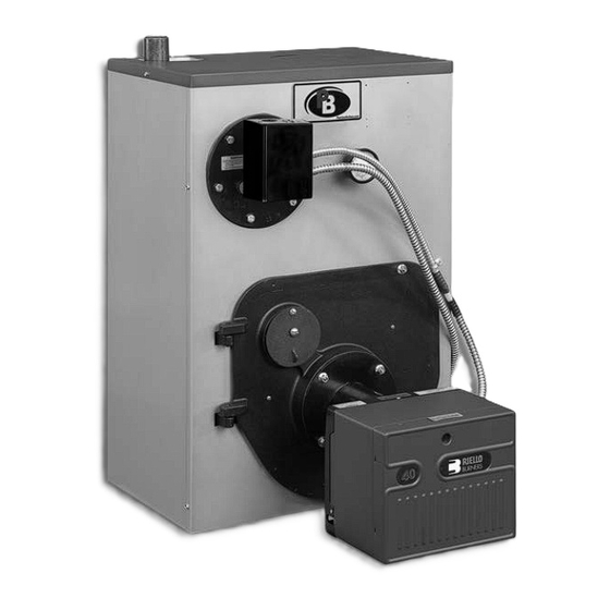
Do you have a question about the WV Series and is the answer not in the manual?
Questions and answers
King Chu
March 27, 2025
I have a wv-DV-04-130 boiler with a Riello burner. The nozzle is 1.1 x 60B . What is the actual firing rate? Why would the factory turbulator setting to 4.0. ? Shouldn’t it be 1.5 instead?
1 comments:
Mr. Anderson
May 14, 2025
The firing rate for the PEERLESS WV-DV-04-130 boiler with a Riello burner and a 1.10 x 60° B nozzle is 1.25 GPH. This firing rate can only be achieved with a Riello F-3 burner.
The factory turbulator setting is 4.0 instead of 1.5 because this higher setting is required to properly mix air and fuel at the higher firing rate of 1.25 GPH, ensuring efficient combustion and performance with the Riello burner.
Page 1
Series WBV/WV ™ Boilers As an ENERGY STAR ® Partner, PB Heat, LLC has determined that this product meets the ENERGY STAR guidelines for energy efficiency. I n s t a l l a t i o n , O p e r a t i o n & M a i n t e n a n c e M a n u a l...
TABLE OF CONTENTS TABLE OF CONTENTS USING THIS MANUAL 5. BURNER SETUP & BOILER OPERATION A. INSTALLATION CLEARANCE ... . .1 A. BURNER INSTALLATION ....14 B.
USING THIS MANUAL USING THIS MANUAL Indicates a condition or hazard which DANGER A. INSTALLATION CLEARANCE will cause severe personal injury, death or major property damage. Follow the installation instructions provided in this manual in the order shown. The order of these Indicates a condition or hazard which WARNING instructions has been set in order to provide the installer...
PREINSTALLATION 1. PREINSTALLATION Read carefully, study these instructions before beginning work. It will save time. Study the included drawings. Save these instructions for reference. This boiler must be installed by a qualified contractor. The boiler warranty can be voided if the boiler is not installed, maintained and serviced correctly. The equipment shall be installed in accordance with those installation regulations in force in the NOTICE local area where the installation is to be made, including the current edition of NFPA-31, Standard...
PREINSTALLATION For Example: C. CHIMNEY / VENT AND DRAFT CONTROL An oil-fired unit shall be connected Comments CAUTION Installation Installation to a flue having sufficient draft at all times, to assure safe proper No change, but older operation of the unit. Chimney chimneys (especially unlined -.04"...
BOILER PLACEMENT AND ASSEMBLY 2. BOILER PLACEMENT AND ASSEMBLY A. SETTING THE BOILER C. JACKET ASSEMBLY (KNOCKDOWN BOILERS) 1. Provide a level foundation, located as close as possible to the center of the heating system. 1. If the boiler is to be installed with a rear flue outlet, remove the square knock-out in the back panel.
Page 7
BOILER PLACEMENT AND ASSEMBLY Figure 2.1: Steam boiler Figure 2.2: Water boiler (See Table 8.1 for parts identification).
PIPING AND CONTROLS 3. PIPING AND CONTROLS Do not pipe boiler before jacket is NOTICE 4. When the return temperature from the system will be installed. below 150°F on oil boilers for extended periods (heat pump systems, outdoor reset, snow melt, etc.), provide piping and controls to protect the boiler from A.
PIPING AND CONTROLS 2. If not using a tankless coil, cover the heater opening E. TANKLESS HEATER OR COVERPLATE with cover plate (item 7 or 16). 1. If a tankless coil is used (item 9), install as pictured. Be sure rubber gasket is in place On water boilers, install in opening in front section.
Page 10
PIPING AND CONTROLS Figure 3.5: Piping to Isolate Boiler from Chilled Medium on Chiller Systems Figure 3.7: Float Low Water Cut-off Figure 3.6: Piping with Peerless ® Indirect Water Tank...
ELECTRICAL 4. ELECTRICAL A. GENERAL All electrical wiring shall be done in accordance with the National Electrical Code and Local Requirements. Single pole switches including those of safety controls or protective devices shall not be wired in a grounded line. IMPORTANT In accordance with Section 325 (f) (3) of the Energy Policy and Conservation Act, water boilers are equipped with a feature that saves energy by reducing the boiler water temperature as the heating load decreases.
BURNER SETUP & BOILER OPERATION 5. BURNER SETUP & BOILER OPERATION Burn only #2 Fuel Oil in this CAUTION 2. Adjust burner and barometric draft control for appliance. Do not use gasoline, highest CO ² (Maximum 13.1%) while maintaining a crankcase drainings or any oil 0 Smoke and a minimum -.01"...
BURNER SETUP & BOILER OPERATION Do not leave boiler unattended while CAUTION E. CLEAN THE BOILER firing burner. Operating boiler with (STEAM BOILERS ONLY) water below minimum permissible water level may fracture sections. 1. Clean the boiler within one week after initial start-up. Cleaning will be more effective if boiler operates a 7.
Page 18
BURNER SETUP & BOILER OPERATION Table 5.1: Beckett Burner Specifications BECKETT BURNER SPECIFICATIONS Start-up Settings Boiler Burner Burner Static Pump Head Nozzle Size Model No. Model No. Head Plate Pressure Setting Air Shutter Air Band WBV-03-085 AFG-F3¹ 3-3/8" 0.75 80° B HAGO³ 140 PSI WBV-03-105 AFG-F4...
MAINTENANCE 6. MAINTENANCE WARNING Product Safety Information Refractory Ceramic Fiber Product This appliance contains materials made from refractory ceramic fibers (RCF). Airborne RCF, when inhaled, have been classified by the International Agency for Research on Cancer (IARC), as a possible carcinogen to humans. After the RCF materials have been exposed to temperatures above 1800°F, they can change into crystalline silica, which has been classified by the IARC as carcinogenic to humans.
MAINTENANCE A. GENERAL C. WEEKLY MAINTENANCE (WITH BOILER OPERATING) 1. Check pipes adjacent to cold walls or in unheated spaces. Insulate and tape them if necessary to be 1. Flush float-type low-water cut-off (if used) to remove sure they can't freeze up. Keeping the water moving sediment from the float bowl as stated in the at all times will reduce the likelihood of freezing.
MAINTENANCE 2. To thoroughly clean the boiler it must be brushed G. IF A LONG SHUTDOWN IS REQUIRED down from the top. Alternatively, for limited space or minimum clearance to combustible installations, 1. To take boiler out of service if the boiler and system cleaning the heat exchanger from the combustion are not to be used when temperatures are below chamber side is acceptable.
BOILER DIMENSIONS & RATINGS 7. BOILER DIMENSIONS & RATINGS Boiler Jacket Jacket Jacket Rear of Jacket Vent Size Model Depth Width Height to c/l of Vent Diameter Number "A" "B" "C" "D" "E" WBV-03-060/085/105 14-1/8" 22-1/8" 35" 7-1/16" 6" WBV-04-095/125/150 18-1/8"...
Page 23
BOILER DIMENSIONS & RATINGS Table 7.1: Boiler Ratings SERIES WBV/WV™ BOILER RATINGS - WATER Series WBV/WV™- water Heating Minimum Capacity AFUE, Stack Input Net Ratings Boiler Water Draft Model Water, Content, Required, Number GPH¹ Water MBH² Water in. W.C. ✚✪ ✸...
REPAIR PARTS 8. REPAIR PARTS Repair parts are available from your local PB Heat, LLC distributor or from Parts To Your Door at 1 (610) 916-5380 (www.partstoyourdoor.com). Note: Remember to include the boiler model number and serial number when ordering parts. Table 8.1 Item Additional...
Page 27
Series WBV/WV ™ Boilers I n s t a l l a t i o n , O p e r a t i o n & M a i n t e n a n c e M a n u a l TO T H E I N S TA L L E R : This manual is the property of the owner and must be affixed near the boiler for future reference.
Need help?
Do you have a question about the WV Series and is the answer not in the manual?
Questions and answers
I have a wv-DV-04-130 boiler with a Riello burner. The nozzle is 1.1 x 60B . What is the actual firing rate? Why would the factory turbulator setting to 4.0. ? Shouldn’t it be 1.5 instead?
The firing rate for the PEERLESS WV-DV-04-130 boiler with a Riello burner and a 1.10 x 60° B nozzle is 1.25 GPH. This firing rate can only be achieved with a Riello F-3 burner.
The factory turbulator setting is 4.0 instead of 1.5 because this higher setting is required to properly mix air and fuel at the higher firing rate of 1.25 GPH, ensuring efficient combustion and performance with the Riello burner.
This answer is automatically generated