Table of Contents
Advertisement
Advertisement
Table of Contents

Related Manuals for PEERLESS WV-DV


Summary of Contents for PEERLESS WV-DV
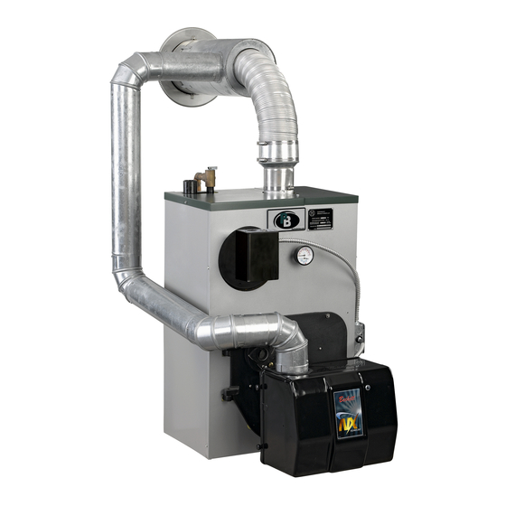
- Page 1 Series WV-DV Boilers ® As an NERGY Partner, PB Heat, LLC has determined that certain firing ® rates of this product meet the NERGY guidelines for energy efficiency. I n s t a l l a t i o n , O p e r a t i o n &...
- Page 2 NOTICE Sidewall Venting The Peerless WV-DV is designed and built to be vented through a side wall of a building using a stainless steel concentric vent terminal (4 inch diameter tube inside an 8 inch diameter tube). Exhaust gases from combustion contain water vapor. During the cooler months of the year, this water vapor will condense into a visible vapor plume.
-
Page 3: Table Of Contents
TABLE OF CONTENTS TABLE OF CONTENTS USING THIS MANUAL 4. VENTING A. INSTALLATION SEQUENCE ... . .2 A. VENT SYSTEM INSTALLATION ...7 B. -
Page 4: Using This Manual
USING THIS MANUAL USING THIS MANUAL A. INSTALLATION SEQUENCE DANGER Follow the installation instructions provided in this Indicates a condition or hazard which will cause manual in the order shown. The order of these severe personal injury, death or major property instructions has been set in order to provide the installer damage. -
Page 5: Preinstallation
PREINSTALLATION 1. PREINSTALLATION Read carefully, study these instructions before beginning work. It will save time. Study the included drawings. Save these instructions for reference. This boiler must be installed by a qualified contractor. The boiler warranty can be voided if the boiler is not installed, maintained and serviced correctly. NOTICE The equipment shall be installed in accordance with those installation regulations in force in the local area where the installation is to be made, including the current edition of NFPA-31. -
Page 6: Boiler Set-Up
Installation,” Page 7, and Figure 4.1. wall (Item 2) is seated in the back of the combustion chamber. (WV-DV-04) Ceramic fiber blanket base 2. Provide a level foundation, located as close as liner (Item 3) should be lying flat on bottom of possible to the center of the heating system. -
Page 7: Piping And Controls
PIPING AND CONTROLS 3. PIPING AND CONTROLS A. BOILER SUPPLY AND RETURN 1. See Figure 3.1 for suggested piping to the boiler. 2. Make up cold water supply connection to the boiler. 3. Plug all open tappings in the boiler and fill with water. -
Page 8: Tankless Water Heater
Figure 3.3 adjustment of controls, refer to the attached control specification sheets. Note: X-1019R, X-1020R and PP-1011R Coils installed in WV-DV boilers have internal flow controls installed. Do not use external flow controls with these coils. C. INDIRECT-FIRED WATER HEATER 1. -
Page 9: Venting
VENTING 4. VENTING NOTICE d. Provide 3' clearance above any forced air inlet within 10'. This boiler is shipped with a Flex-L International Vent Terminal carton, and a Flex-L International Venting e. Provide 4' clearance below, 4' beside, or 1' above Components Kit. - Page 10 VENTING 2. Use Flex-L International Inc. 4" diameter CeraFlex Vent Pipe. 3. For air intake, use 4" diameter galvanized smoke pipe or 4" diameter flexible corrugated aluminum pipe. Maximum equivalent length of galvanized smoke pipe is 40'. Allow 5 equivalent feet for each 90°...
-
Page 11: Oil Burner
OIL BURNER 5. OIL BURNER CAUTION 6. Burner should start automatically when thermostat is turned up and main boiler service switch is turned BURN ONLY #2 FUEL OIL IN THIS APPLIANCE. DO on. If burner does not start, check to be sure there is NOT USE GASOLINE, CRANKCASE DRAININGS OR oil in the tank and push reset button on burner ANY OIL CONTAINING GASOLINE. - Page 12 OIL BURNER Table 5.1 Beckett NX Burner Specifications Boiler Model No. Burner Model Nozzle Manufacturer, Size Pump Pressure (psig) Head/Air Setting Low Fire Baffle WV-DV-03-075 NX70LB Delavan 0.60 60° W¹ 2.25 WV-DV-03-085 NX70LB Delavan 0.65 60° W 3.00 WV-DV-03-110 NX70LB Hago 0.85 60°...
-
Page 13: Electrical
ELECTRICAL 6. ELECTRICAL A. WIRING B. ZONED SYSTEM WIRING 1. Wire zone circulators as shown in Figures 6.4 and 1. All electrical wiring shall be done in accordance with 6.5. Wire zone valves as shown in Figure 6.6. the National Electrical Code and Local Requirements. - Page 14 ELECTRICAL Figure 6.3: Riello Burner Figure 6.4: Zoning With Circulators, Honeywell L8148 Aquastat...
- Page 15 ELECTRICAL Figure 6.5: Zoning With Circulators, Honeywell L8124A, C Aquastat Figure 6.6: Zoning With Zone Valves...
- Page 16 ELECTRICAL Figure 6.7: Partner with Circulator (Non-priority)
-
Page 17: Maintenance
MAINTENANCE 7. MAINTENANCE WARNING Product Safety Information Refractory Ceramic Fiber Product This appliance contains materials made from refractory ceramic fibers (RCF). Airborne RCF fibers, when inhaled, have been classified by the International Agency for Research on Cancer (IARC), as a possible carcinogen to humans. After the RCF materials have been exposed to temperatures above 1800°F, they can change into crystalline silica, which has been classified by the IARC as carcinogenic to humans. -
Page 18: Cleaning Heating Surfaces
MAINTENANCE A. CLEANING HEATING SURFACES NOTICE NOTICE Combustion chamber cover plate must be opened to facilitate this operation. Entire heating system, including boiler, burner and 5. Replace oil burner and flue collector cover plate venting system, must be inspected at least once a making sure all gaskets are in place. -
Page 19: Boiler Dimensions & Ratings
BOILER DIMENSIONS & RATINGS 8. BOILER DIMENSIONS & RATINGS Model Figure 8.1: WV-DV Boiler Views WV-DV-03 14 " " WV-DV-04 18 " " Table 8.1: WV-DV Ratings Boiler Heating Net I=B=R Ratings I=B=R Model Capacity BTU/Hr. Firing Number BTU/Hr. Water Rate G.P .H. -
Page 20: Repair Parts
REPAIR PARTS 9. REPAIR PARTS Repair parts are available from your installer or by contacting PB Heat, LLC, P .O. Box 447, New Berlinville, PA 19545-0447. Note: Remember to include boiler model number and serial number when ordering parts. Figure 9.1: Repair Parts... - Page 21 REPAIR PARTS Table 9.1: Repair Parts** Item Additional Stock Code Stock Code Description Information WV-DV-03 WV-DV-04 — 90183 90184 Block Assembly Water WPCT — 90186 90187 Block Assembly Water WPC — 50795 50795 Target Wall Base Liner — — 50857 —...
- Page 22 NOTES...
- Page 23 NOTES...
- Page 24 Series WV-DV Boilers I n s t a l l a t i o n , O p e r a t i o n & M a i n t e n a n c e M a n u a l...
Need help?
Do you have a question about the WV-DV and is the answer not in the manual?
Questions and answers