Table of Contents
Advertisement
Advertisement
Table of Contents

Related Manuals for PEERLESS SERIES 62


Summary of Contents for PEERLESS SERIES 62
- Page 1 61/62 Boilers Installation, Operation Maintenance Manual...
- Page 2 Steam Boilers Peerless Heater Comparly is pleased to offer of the most comprehensive warranty programs PGGRLESS icl tile indnstn 1, All Peerless residential cast troll _x_ilers include a fidl one-yea" warranty. A limited. lifetone warranty is provided.for cast iron sections...
- Page 3 Series pr=-I RLESS o Residential Gas Boilers • Packaged or Knockdown o Natural Draft Venting o Standing Pilot or CAST IRON BOILERS Spark Ignition Q Steam or Hot Water Boilers o Natural or LP Gas Q This large water content boiler installs in difficultsteam or water applications.
- Page 4 (It't' /loll' ttl'(li[(l!)_('. CAST IRON BOILERS !'lt>(_._;( ' €'otl.'_ll/I I>_'('t'l_ '.'q_ I h'_ll_'t ( "olllt)_lltt].[O_" _'Oml)lt'f_" it,t_r_t_i_l!] ir!]Oi rIl(llioll. Peerless Heater Company • 231 North Walnut Street * Boyertown. 19512 1021 • 610 367-2153 - www.peerless-heater.com FAB 6_7 t9 02 :_,%...
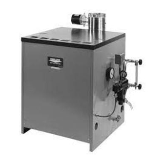
- Page 5 pGr=-RLESS o Series o Semi-Commercial Gas Boiler • Packaged or Knockdown o Natural Draft Venting o 320 to 560 MBH Input CAST IRON BOILERS o Steam or Hot Water Boilers o Natural or LP Gas o The large water content of this knockdown or completely packaged boiler makes it ideal for difficult steam or water applications.
- Page 6 Steam Water 3/4" Pressure Gauge* Limit Control (Models 09-11) 3/4,, Operating Control (Models 12-15) 3/4" Limit Control (Models 12-15) V2" Temperature-Pressure Gauge V2" Gauge Glass and Low Water Cutoff 2" Return Return 3/4" Secondary Probe Low Water Cut-Off 3/4" Safety Relief Valve Safety Relief Valve 1V2"...
- Page 7 STEAM WATER "L NOTE: Provide Tee, Nipple and Cap Fittings below water line to assist in cleaning or draining. Steam Boiler Model Number Size of Outlets No. Supply Outlets Header Supply Equalizer Size 62-09 1V4" 2" 3 _= 62-10 11/4" 2"...
- Page 8 SERIES 62 BOILER SPECS _-_-_ LlJl-J_vd_id • Cast Iron Sections--Factory Tested and Approx. Shipping Wts. (Ibs.) Assembled with Steel Push Nipples Boiler Model • Deluxe Insulated Enameled Steel Jacket Number I Length I Width ! Height • Drain Valve • Horizontal to Vertical Draft Diverter 62-09 57"...
- Page 9 Read carefullybeforebeginningwork.It witlsavetime.Studythe includeddrawings. The equipmentshallbe installedin accordancewith thoseinstallationrequirements of the authorityhavingjurisdictionor, in the absenceof such requirements, t o the current editionof the NationalFuelGas Code Z223.1/NFPA54. Whererequiredbythe authorityhavingjurisdiction,the installationmustconformto the standardforControlsand SafetyDevicesfor AutomaticallyFired Boilers,ANSI/ASMECSD-I. A - ACCESSIBILITY CLEARANCES 1. Toprovidefor reasonableconditionsof accessibility, t he followingminimumclearancesare recommended. a.
- Page 10 D - SE'I-rlNG UP BOILER - UNASSEMBLED UNITS I-- ASSEMBLEDBLOCKS 1--The boilersections andbase,Models61-03thru61-07arefactory assembled. Remove shippingskidfrom the boiler base.If boilerisa 61-08, or 62-09thru62-15beginassembly as noted in PartII "SplitBlock Assembly". 2--Providea goodlevelfoundation, The Boiler s hould be located as neartothechimney andcentralized withrespect t othe heating system as possible.
- Page 11 FOR STACKING PALLtr'rq I:'ROC_"OUR lr II-- SPLITBLOCKASSEMBLY 1--Boiler sectionsfor Models61-08,62-09thru 62-15are shippedin two parts. Removeskidfrom each blockof sections. 2--Place each blockof sectionson the stackedskids.See Fig.A. Be certainto removethe small blockson the top skid.See Fig.B, 3--To clean nippleportsand removeprotectivecoating, use a wire brush andmineralspiritsor lacquerthinner.Makecertainthereare no burrs aroundthe outsideedgeof the ports.
- Page 12 6. Place the Secondary Air Cover Door atbottom ofInner Front Panel. The t op bend ofthe Cover Door slips o ver the top reverse bend atcut o ut opening ofthe inner Front Panel. Refer toFigure 11. 7. Atlach Draft Hood toFlue C ollector with t wo (2) #10 x 1/2"...
- Page 13 JACKET ASSEMBLY FIGURE 4 RATINGLABEL LIGHTING/OPERATING INSTRUCTIONSLABEL (61-63 THRU 62-11) LIGHTING INSTRUCTIONSPLATE (62-12 THRU 62-15) CITYOFNEW YORK • MEAPLATE (WHEN REQUIRED) " WIRING CLEARANCETO COMBUSTIBLESPLATE DIAGRAM LABEL REMOVABLEFRONT PANEL INNER FRONT PANEL (INSIDE VIEW) AGENCY LABEL & PLATE LOCATIONS FIGURE 5...
- Page 14 FIGURE 6 FIGURE 7 FRONT BOILER VIEW FRONT TOP BOILER VIEW T_6"- !_UNC & WASHER _BASE BACK PLATE BURNER MANIFOLD-_ HOOK BOLT _'w FIGURE 9 HOOK BOLT ASSEMBLY FIGURE 10 FIGURE8 REAR BOILERVIEW FLUE COLLECTOR/DRAFT HOOD FIGURE 11 -"IGURE 12 SIDE VIEW OF INNER FRONT TOP CUT VIEW OF MANIFOLD AND COVER DOOR...
- Page 15 F - VENTING A. General 1--For connectionto gasvents or chimneys,vent installationshall be in accordancewith Part7, Ventingof Equipment, o f the currenteditionof the NationalFuelGas Code,ANSIZ223.1/NFPA54, o r applicableprovisionsof the localbuildingcodes. 2--Draft: Sufficientdraft mustbe availableforremovalof productsof combustion. I f draft is not adequate,spillageof the productsof combustion will occurat the bottomoutletof the draft hood.
- Page 16 B,VentDamperInstallation 1 Ventdampers are providedon models61-03through 61-08as standardequipment. 2--Unpack the vent damperandfollowthese instructionsandthe installationinstructionsin the vent dampercarton.Observethe cautionsand warmngthat accompanyall instructions. D o not modifyvent damperor boilerdraft hood 3--The vent dampercan be mounteddirectlyonto the drafthood outletcollar,or in the vent pipingclose to the boiler.Seefigures14 and 15, Be sure directionof flow arrow locatedon dampercollar,is pointingawayfrom draft hoodcollar and damperpositionindicatoris visibleafter installation,For installationwithdampermountedin the horizontalposition,mountthe damperas shownin figure 15 to avoid excessiveheat and possiblecondensationdrips on the damperoperatingcontrol.
- Page 17 SLOPE UP A MINIMUM OF 1/4" PER FOOT VENT DAMPER AS REQUIRED DRAFT HOOD OUTLET Figure14:Venting with VentDamperin VerticalPosition /- VENT TO SLOPE UP VENT /CHIMNEY A MINIMUM DAMPER oF1/4" "7F" 1 1 O'CLOCK PER FOOT_ 11 O'CLOCK POSITION OPERATOR -CONDENSATION ZONE 7 O'CLOCK...
- Page 18 G - PIPING 1--Hot Water: a.The recommended pipinghook-upis shownin Figure17.Also referto PeerlessWaterSurvey. 2--Steam: a.The recommended pipinghook-upis shownin Figure16. Pleasenotethat a Hartfordreturn loop is recommended to be usedon all steam boilers.Also referto PeerlessSteam Survey. 3--The reliefvalveand popsafetyvalveshallbe installedby usingthe 3/4"x 3"nippleand 3/4" elbow suppliedwith the boiler.Referto illustrations located inSection R - "Ratings,Tappings and Dimensional D ata".LargeNPT sizevalvesmay be installedin supplypiping.
- Page 19 Table1: SteamHeader, R isersand EqualizerSizing Model No. Supply Size of Header Equalizer Outlets Outlets Supply Size 6t-03 2" 1114" 61-04 2" 11/4" 61-05 2" lr_" 61-06 2" 21_" 11_" 61-07 2+/2" 11_" 2" 61-08 2" 11_" 3" 62-09 2" 3" 11_"...
- Page 20 SERVICE _JACKET G.J. UNION SEDIMENT TRAP _./FLOOR LINE Figure18: ParallelHook-UpwithWater Chiller Figure19:Gas Connectionto Boiler Figure20: GravityHotWater Figure21: ForcedHotWater .HIGH TEMPERATURE HEATER WATER _. MIXEO "rAPPING WATER MIXER Figure22: SteamW/FloatLWCO Figure23: SuggestedPipingForTanklessHeater...
- Page 21 THRU i1_11 TAPPINGS TO MOUNT LONG GAUGE GLASS FROM PROBE L.WC.O. CARTON © © Figure21A RIGHT SIDE PANEL Figure24: Steam:PrimaryProbeLWCO,Hydrolevel C G400P IMPORTANT 1. Inspect P robeElectrodeannuallyfor scaleandbuild-upand clean if necessary. 2. Forpropermaintenance, recommended w aterfeeder applications andoperation,referto the Hydrolevel ProbeLWCOInstallation I nstructions. •...
- Page 22 I - CONTROLS l--Steam: a.For proper }ocationof controlsand accessoriesreferto SectionR "Ratings,TappingLocations a ndDimensional D ata". b.The McDonnell& Miller #67PE-2LWCOis furnishedas a standardwith all steamboilers.The Hydrolevel C G 400-PPrimaryProbeLWCOis optional.This control providesa lg minuteon cyciefollowedby a 90 secondoff cycle.This featureallowsthe waterlevelinboilerto settleso that the probe can sensea true waterlevel.
- Page 23 3--Specific details regardingthe installationof the variouscontrolsare givenin the controlsheetsattached. 4--In the eventof a controlfailurethe replacementshallbe identicalwiththe originalequipment. certain modelsa separatepilot switchmustbe used.The switchshallbe mountedon the left sideof the inner frontjacket panel.Usethe two Ys"holes provided,if holesare not provided,drill accordinglyas shownin Figure45. 6--For Models61-08,62-09thru 62-16the sparkignitioncontrolbox whensupplied,mustbe mountedon the outerleft side jacketpanel asshown in Figure43.
- Page 24 L1 - ADJUSTMENT TO GAS PRESSURE REGULATOR 1--Set manifoldpressureasfo_lows for various gases. a. Natural Gas....31/2"WaterColumn b, LiquefiedPetroleumGas ....10" WaterColumn 2--To adjustgas pressure,turn adjustingscrewof gas pressureregulator,out to decreasepressure,turn in to increasepressure,Referto control sheetssuppliedwith boilerfor locationof gas pressureregulator• 3--In no case shouldthe finalmanifoldpressurevary morethan plusor minus03 incheswatercolumnfrom the abovespecifiedpressures• Any necessarymajorchangesinthe flowshouldbe made by changingthe sizeof the burnerorifice.
- Page 25 HONEYWELL 24V STANDING PILOT - STEAM w/DAMPER, FLOAT LWCO AND ISOLATION RELAY Models61-03 thru61-08 TST_ _LA¥ COIL R _ RELAY _TUB _AP,NES$ _ADC,CR LEr_ND LINE VOLTAGE LO_ VOLTAGE H V88_ Figure28 HONEYWELL 24V STANDING PILOT - STEAM OR GRAVITY HOT WATER Models62-09 thru 62-11 r_'f_ Figure29...
- Page 26 HONEYWELL SPARK IGNITION (HSP) - GRAVITY OR STEAM w/DAMPER, FLOAT LWCO AND ISOLATION RELAY Models 61-03thru61-07 TRANSFORME_ 120V _J_J_J TSTAI F_EL A_" COIL _R L SpARK ilrl IAODER tECENO :IN_ VOLTAGE _OW VOL_SE Figure30 HONEYWELL SPARK IGNITION (HSP) - FORCED HOT WATER w/DAMPER Models61-03thru 61-07 4_OJTJL_ ?v"...
- Page 27 HONEYWELL SPARK IGNITION (HSP) - FORCED HOT WATER w/COIL AND DAMPER Models 61-03thru61-07 _--_ .._-rr'ccc_.._'- ..- ....i..L .... _w ..L I i _ L ..__'..iJ__J z-__.,qt_ • .._---= __=__-_2 • __+J L_IN_ _,rAG_ 14 _...
- Page 28 HONEYWELL SPARK IGNITION (HSP-1) - w/DUAL 24V MAIN GAS VALVES Models 62-09thru 62-15 [ ...._,L W_ _,V___ _ICA_[ COOlS. C,_O_',_ES. A_ _1'_ A_IC,_S, Figure34 HONEYWELL SPARK IGNITION (HSP-1) - w/DUAL 120V MAIN GAS VALVES Models 62-09Thru62-15 .."F ....
- Page 29 WIRING APPLICATION OF HYDROLEVEL PROBE LOW WATER CUTOFFS Models 550P,650P andCG550P Referto SectionI - Controlsof this manualfor mountinglocationand instructions. 115V-60HZ L1 (HOT) £ --I1_- 115V-60HZ ALARM CIRCUIT TO L2 ON (WHEN REQ'D) WIRING DIAGRAM _, L1 ON WIRING DIAGRAM NOTES: ALL WIRING MUST COMPLY W!TH APPLIANCE CCDE3,...
- Page 30 The followingwiring diagrams,figures37 thru 42, are for use with a Hydrolevel C G400-P ProbeLWCO HONEYWELL 24V STANDING PILOT - STEAM w/DAMPER AND HYDROLEVEL PROBE LWCO Models 61-03thru61-08 C_,INEC_ _A_AU H_ESS _SCON_J_T _¢ S_TC _ mANSF_ 4OVA PROBE C_I_t -- - x---_ i___w w/ _...
- Page 31 HONEYWELL SPARK IGNITION (HSP) - STEAM w/DAMPER AND HYDROLEVEL PROBE LWCO Models 61-03thru61-07 CO_EClrO_ I_AGRAM MRE HARNESS T_N_FORME _ i i]ilZSS] .... T,E,.O_,,T L ..I_,% •_,,---,_---.1_ ..;g Fo _ "p ..@..<_ rR S L W¢O u_m_ TRAN_C_M( R "l *,OVA...
- Page 32 HONEYWELL SPARK IGNITION (HSP-1) - w/DUAL 24V MAIN GAS VALVES AND HYDROLEVEL PROBE LWCO Models 62-09thru62-15 .... Ti IRANsrO_E_ (HOt) _J3LLLt_ _'Iv ..VAL_ LING VOtT;_C[ EXT_F_N_L _e,NG Figure41 HONEYWELL SPARK IGNITION (HSP-1) - w/DUAL 120V MAIN GAS VALVES AND HYDROLEVEL PROBE LWCO Models 62-09thru62-15 CONNCC_ON DIACP,_ U (H°T)
- Page 33 BOILERS E QUIPPED WITH CONSTANT BURNING P ILOT HONEYWELL GAS VALVE LIGHTING INSTRUCTIONS NOTE: C HECK WATER LINE OFSTEAM BOILER, ORBECERTAIN S YSTEM ISFULL FOR WATER BOILER, BEFORE PROCEEDING WITH THESE INSTRUCTIONS. FOR YOUR SAFETY READ BEFORE LIGHTING WARNING: If you do not follow these instructions exactly, a fire or explosion may result causing...
- Page 34 BOILERS EQUIPPED WITH ELECTRIC IGNITION AND A COMBINATION GAS VALVE OPERATING INSTRUCTIONS NOTE:CHECKWATER LINEOF STEAMBOILER, O R BE CERTAIN SYSTEMIS FULL FORWATERBOILER, B EFOREPROCEEDING WITHTHESEINSTRUCTIONS. FOR YOUR SAFETY READ BEFORE OPERATING WARNING: If you do not follow these instructions exactly, a fire or explosion may result causing property damage,...
- Page 35 Refer t o Figure 43withthefollowing instructions BOILERS EQUIPPED WITH ELECTRIC IGNITION AND DUAL GAS VALVE LIGHTING INSTRUCTIONS NOTE:CHECKWATERLINEOF STEAMBOILER,OR BE CERTAINSYSTEMIS FULL FORWATERBOILER,BEFOREPROCEEDING WITHTHESEINSTRUCTIONS. FOR YOUR SAFETY READ BEFORE LIGHTING WARNING: If you do not follow these instructions exactly, a fire or explosion may result causing property...
- Page 36 SIAqK IGNITED pILOT _STO. PILOT IGNITI BLEED TUBING --VENT TO 118*q BLEED TU6E OR TO OUTSIDE ATMOSPHERE WELL /M3OVE NORMAL _REATHING LEVEL APPLICABLE I/4" TEST PILOT VALVE PILOT pILOT COCK MANUAL S:_UT -OFF VALVE THERMOCOUPLE LEAD IGNITION CONTROL LEFT SIOC JACKET PANEL Figure43: HSPControlSystemand IgnitionControlBox Location...
- Page 37 Refer t o Figure 44withthefollowing instructions BOILERS EQUIPPED WITH ELECTRIC IGNITION AND A COMBINATION GAS VALVE OPERATING INSTRUCTIONS NOTE:CHECKWATERLINEOF STEAMBOILER,OR BE CERTAINSYSTEMIS FULL FORWATERBOILER,BEFOREPROCEEDING WITHTHESEINSTRUCTIONS. FOR YOUR SAFETY READ BEFORE OPERATING WARNING: If you do not follow these instructions exactly, a fire or explosion may result causing property damage, personal injury, or loss of life.
- Page 38 SpAR_ IGNkTEO PLLOT VALVE PILOT COCK lLO__T _ VALVE Figure44:HSP-2 ControlSystem Model61-08...
- Page 39 Refer to Figure 45withthefollowing instructions BOILERS EQUIPPED WITH CONSTANT BURNING PILOT(S) LIGHTING INSTRUCTIONS NOTE: CHECK WATER LINE OFSTEAM BOILER, ORBECERTAIN SYSTEM IS FULL FOR WATER BOILER, BEFORE PROCEEDING WITH THESE INSTRUCTIONS. FOR YOUR SAFETY READ BEFORE LIGHTING WARNING: If you do not follow these instructions exactly, a fire or explosion may result causing property damage, personal...
- Page 40 I/8"BLEED PI_ESSURE REGULATOR _/_INNER FRONT J,t*CKET PANEL F_LOT THERMC_ILOT I/4" TEST MAIN SAFETY ]'F_- 16_" T PERMOCOUPLE FLOO LINE Figure45:24 VoltControlSystemw/DualValves Models61-08,62-09thru 62-11...
- Page 41 0 - INSTRUCTIONS FOR OPERATION 1--The installationisnot completeuntil Ratingand LightingPlatesareon the boilerandthe"UsersInformation M anual"and "Installation Instructions" are hung near the boiler 2--System shouldbe maintainedin good repair.Radiators,baseboardunits and/orconvectorsmustbe kept clean. :_lf a radiatordoes not heat all over.air has probablyaccumulatedandshouldbe vented. P- CHECKOUT PROCEDURE 1--After startingboiler,be certain all controlsare workingproperlybeforeleavingit unattended,Checkto be sure thatthe temperaturelimitcontrol will shut off the boilerin the eventof excessivetemperature,by loweringlimitset pointuntil mainburnersshut down,Returnlimitto desiredset point.
- Page 42 Cleaning the Series 61162Steam Boiler with Skim Tapping Thefollowing c leaning procedure shallbe performed bya qualified serviceperson. 1. Cleanthe boiler as described below no laterthanoneweekafterthe initial s tart up, Cleaningwillbe moreeffectiveifthe boiler operates a day or twoto loosen sedimentand impurities i n thesystem. 2, Theboiler mustbe cleaned to remove anyaccumulatior_ o foil, grease,sludge, e tc.thatmaybein the system, Thesesubstances c ancause foamingand surgingof the boilerwater,producingan unstablewaterline andwatercarryoverto the system, WARNING:CLEANINGTHE BOILERREQUIRES THE USEOF VERY HOTWATER AND CORROSIVE CHEMICALS.
- Page 43 R - RATINGS, T APPINGLOCATIONS AND DIMENSIONAL DATA SERIES 61 ,7_,E,, 'D" 2 SUPPLY lAPPING "F' INLET_ "" 5" _ _,_"A"_ B' _ Lz_' LEFT SIDE FRONT RIGHT SIDE SERIES 61 TAPPING LOCATIONS Location Size N.RT. Steam Water 3/4,, Limit C ontrol PressureGauge"...
- Page 44 / ,,/ I_LET_ _ .5' 'kff_ ÷ VALVE 161_ _ FLOOR LINE _I-LI_4! LYe' _'A'_' BI,, _ LEFT SIDE FRONT RIGHT SIDE SERIES 62 TAPPING LOCATIONS Location Size N.RT. Steam Water 3/4. Pressure Gauge* LimitControl/Models 09-11) 3/4. OperatingControl(Models12-16) 3/4" LimitControl(Models12-15) 1/2"...
- Page 45 S - MAINTENANCE AND INSPECTION 1--This boilermustbe disconnected from the gas supply pipingduringany pressure testingof thesystem.RefertoSectionH - "GAS PIPING". Note 8 for details. 2--The gas vent usedon this boi{erisof the horizontalto verticaltype.Thevent andventingsystemshouldbe inspectedthoroughly at the beginningof eachheatingsystem. 3--The area wherethe boileris contained should be clearand free from combustible materials,gasolineandotherflammablevapors and liquids. The boilerarea shouldhaveample air for combustionandventilationand thereshouldbe no obstructionspreventinga free flow of air 4--AI1low watercut-offsshouldbe tested and inspectedper manufacturer's instructions, a ny float types shouldbe flushed on a weeklybasisto removeany sedimentfrom the float bowl.
- Page 46 REPAIR PARTS SERIES 61/62 GAS BOILERS REPAIR PARTS ARE AVAILABLE FROM YOUR INSTALLER OR BY CONTACTING PEERLESS HEATER COMPANY,BOYERTOWN, PA 19512-0855 NOTE: REMEMBER TO INCLUDE BOILER MODEL NUMBER AND SERIAL NUMBER WHEN ORDERING PARTS. Part No. Item No. Description AdditionalInformation...
- Page 47 AdditionalInformation Item No, Part No. Description Jacket Assembly Specify BoilerModel TheraltimeterGauge Steam Gauge Gauge Glass Bet 3/4"DrainCock LightingInstructionPlate SpecifyControl System Lighting/Operating Instructions Label SpecifyControl System HighTemperatureSealing Cement SpecifyQuantityof Containers 1/2"Pint Can NippleSealer SpecifyQuantity 1/4"AluminumTubing Specify Quantityin Feet Water Trim SteamTrim w/LWCO GasValve SpecifyBoiler Model,Control System,Typeof Gas Pilot...
- Page 48 TO THE OWNER: This boiler should inspected annually Qualified Service Agency. HI Division ASME af gama PEERLESS BOILERS www.peerless-heater.com @2003 Peerless Heater Company P8207 R23 (3/03-2,5M) Printed in U.SA.
Need help?
Do you have a question about the SERIES 62 and is the answer not in the manual?
Questions and answers