
Subscribe to Our Youtube Channel
Related Manuals for ESAB ARC 601i


Summary of Contents for ESAB ARC 601i
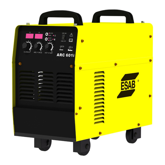
- Page 1 ARC 601i INVERTER MMA / GOUGING Welding Power Source Instruction manual Ver: 1.0 0421...
- Page 2 ARC 601i INVERTER WELDING POWER SOURCE Instruction manual Installation, Operation & General maintenance...
-
Page 3: Table Of Contents
CONTENTS Item Page No. SAFETY RATING AND INSTALLATION CAUTIONS FOR INSTALLATION WELDING OPERATIONS WIRING DIAGRAM GENERAL MAINTENANCE PARTS LIST AND EXPLODED VIEW 12-15 ESAB INDIA CONTACT DETAIL... -
Page 4: Safety
SAFETY Users of ESAB welding equipment have the ultimate responsibility for ensuring that anyone who works on or near the equipment observes all the relevant safety precautions. Safety precautions must meet the requirements that apply to this type of welding equipment. The following recommendations should be observed in addition to the standard regulations that apply to the workplace. - Page 5 WARNING Arc welding and cutting can be injurious to yourself and others. Take precautions when welding. Ask for your employer’s safety practices which should be based on manufacturers’ hazard data. ELECTRIC SHOCK – Can kill • Install and earth the welding unit in accordance with applicable standards.
- Page 6 RATING RATING OF ARC 601i INVERTER WELDING POWER SOURCE Contents of parameters Unit ARC601i No-load voltage Working voltage 22-44 Rated welding current Output Welding current 50-600 regulating range 100% Rated load duty cycle 520A 600A Number of phases Phase Frequency...
- Page 7 INSTALLATION Input wiring Ensure that the voltage, number of phases, frequency and capacity of the input power are consistent with the calibration values on the nameplate of the welding machine. Wiring shall be performed by professional electrician. The input cable and air inlet are located on the back panel of the welding machine. Please refer to the structure diagram of welding machine for detailed location.
-
Page 8: Cautions For Installation
CAUTIONS FOR INSTALLATION − Provide a Switch Box for every Welding Power Source, and use designated fuse − Tolerance of Power Voltage Variation is 10% of rated input voltage. a) Installation place − Install in the place where less moisture and dust exist. Avoid direct sunlight and rain and maintain ambient temperature within –10 to +45 as much as... -
Page 9: Welding Operations
WELDING OPERATIONS The power switch of the welding machine is located on the upper part of the rear panel of the welding machine. Turn on the power switch of the welding machine and the welding machine will be on. The power indicator light of the welding machine on the front panel will be on (the green light will be on), the digital display will display value, the fan will start running, and the output voltage will be available. - Page 10 VRD ON / VRD OFF VRD function can be switched to ON or OFF condition. Digital display will show output current value in AMP and output voltage value in Volt.
-
Page 12: General Maintenance
General maintenance No additional maintenance for fan is required as all parts of the fan are sealed. If the welding machine is used where there is a lot of dust, the dust may block the air duct of the welding machine and cause the welding machine to heat up. Therefore, it is necessary to use dry compressed air to remove the dust inside the welding machine at set intervals. -
Page 13: Parts List And Exploded View
Parts List and Exploded view PART NO DESCRIPTION 0012001004 4-CORE AVIATION SOCKET ARC601i 0040214018 OUTPUT TERMINAL ARC 601i 0010603056 WELDING CURRENT KNOB ARC 601i 0030101884 CONTROL PANEL ARC 601i 0010603057 PUSH CURRENT KNOB ARC 601i 0010603057 ARC STRIKE CURRENT KNOB ARC601i 0011504006... - Page 14 0011501003 MINIAT.CIRCUIT BREAKER ARC601i 0050802003 CABLE CONNECTOR ARC 601i 0030501596 INPUT CABLE ARC 601i...
- Page 15 0011702012 AXIAL FLOW FAN ARC 601i 0060301221 F.REC'RY DIODE RADIAT.ARC601i 0012102033 F.REC'ERY DIODE MODULE ARC601i 0030604330 F.REC'RY DIODE MOD (CU B.BAR) ARC601i 0030101676 DIODE ABSORPTION BOARD ARC601i 0031001123 THREE-PHASE INPUT CABLE ARC601i 0060101171 CONTROL TRANSFORMER ARC 601i 0030101831 TIMING DRIVE BOARD ARC 601i...
- Page 16 ABSORPTION BOARD ARC 601i 0030801644 MAIN TRANSFORMER ARC 601i 0010227001 CAPACITOR ARC 601i 0011303003 CURRENT TRANSFORMER ARC 601i 0031001122 PRIMARY SIDE INDUCTOR ARC 601i 0010110030 CEMENT RESISTOR ARC 601i 0012103002-01 3PH REC'ER BRIDGE MOD. ARC601i 0010114003 VOLT.DEPE'NT RESISTOR ARC 601i 0011304008...
- Page 17 ESAB INDIA LIMITED Registered and Head Office 13, Industrial Estate, III Main Road Ambattur, Chennai - 600058 Telephone: + 91 44 42281100 Fax: + 91 44 4228 1107 Email: info@esab.co.in Web: www.esabindia.com...
Need help?
Do you have a question about the ARC 601i and is the answer not in the manual?
Questions and answers