
Related Manuals for Jøtul F 171 ZENSORIC


Summary of Contents for Jøtul F 171 ZENSORIC
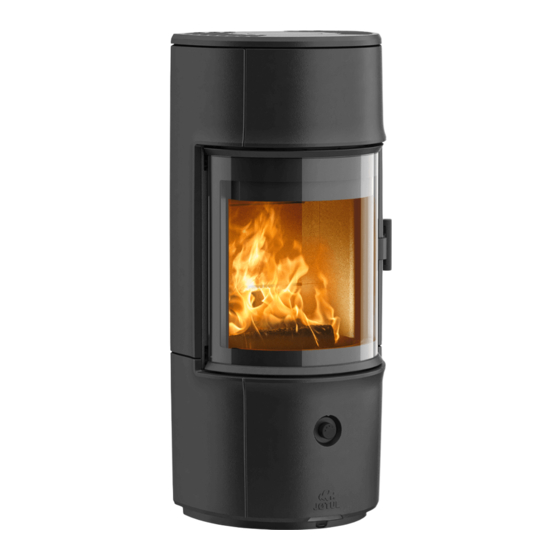
- Page 1 Jøtul F 171 ZENSORIC Jøtul F 174 ZENSORIC Jøtul F 176 ZENSORIC Since 1853 OPERATING INSTRUCTIONS Jøtul AS, P.o. box 1411 N-1602 Fredrikstad, Norway intl.jotul.com...
-
Page 3: Table Of Contents
INNHOLD FIRST TIME ...............23 “TOP DOWN” LIGHTING THE FIRE ......23 RELATIONSHIP TO THE ADDING FIREWOOD ..........23 AUTHORITIES ........4 EXTERNAL AIR SUPPLY ..........24 HEATING ADVICE .............25 TECHNICAL DATA ......4 WOOD CONSUMPTION...........25 WARNING AGAINST OVERHEATING .......25 SAFETY ..........5 REMOVING ASH............25 FIRE PREVENTION MEASURES ........5 OPERATION UNDER DIFFERENT WEATHER CONDITIONS ............25 FLOOR ................5... -
Page 4: Relationship To The Authorities
fi replace. External air connec on Alu. fl ex - Ø 100 mm Vekt Jøtul F 171 Zensoric 148 kg Read the Installa on instruc ons with technical data and the Vekt Jøtul F 174 Zensoric... -
Page 5: Safety
SAFETY To guarantee op mal performance and safety, Jøtul recommends that its stoves are fi ed by a qualifi ed installer (see The func on of a fl oor plate is to protect the fl oor and fl ammable www.jotul.com for a complete list of dealers). materials against embers. -
Page 7: Dimensions
DIMENSIONS JØTUL F 171 ZENSORIC, JØTUL F 174 ZENSORIC AND JØTUL 176 ZENSORIC 900371-P00... -
Page 8: Minimum Distances
MINIMUM DISTANCES JØTUL F 171 ZENSORIC, JØTUL F 174 ZENSORIC AND JØTUL 176 ZENSORIC F 620: MIN. DISTANCE TO COMBUSTIBLE WALL F 620: MIN. DISTANCE TO COMBUSTIBLE WALL 900371-P00... -
Page 9: Installation
INSTALLATION CHIMNEY AND FLUE PIPE • The fi replace can be connected to a chimney and fl ue pipe approved for solid fuel fi replaces with fl ue gas temperatures as specifi ed in “Technical Data”. If a steel chimney is used, this must be marked with T 400 and G for soot fi re tes ng. •... -
Page 10: Prior To Installation
PRIOR TO INSTALLATION • Before installing the fi replace, check it carefully for any signs of damage • The product is heavy! Ask someone to help you when posi oning and installing it. We recommend using a li ing device. •... - Page 11 PRIOR TO INSTALLATION TIP: Place the knob by the door to keep the door open.
-
Page 12: Removal Of Transport Protec On
REMOVAL OF TRANSPORT PROTECTION Li the lower baffl e plate, remove transport Turn the guide plate 90° and lower it out through the combus on chamber protec on and the pin Li the upper baffl e plate and remove protec on Mount again the upper baffl... -
Page 13: Setting Of Electronic Air Control
SETTING OF ELECTRONIC AIR CONTROL The electronic air control on Jøtul F 170 Zensoric run in 3 levels: Step 1 - Suitable for so wood, e.g. fi r, pine, poplar, willow Step 2 - Suitable for between hardwoods, e.g. birch, maple, or mixed hardwood Step 3 - Suitable for hardwood, e.g. -
Page 14: Height Adjustment Of Wood Stove
PRIOR TO INSTALLATION Make sure the diode is in place as shown below. HEIGHT ADJUSTMENT OF WOOD STOVE The stove has four adjustment screws under the stove. Use the adjustment screws to get the stove to stand straight and level. NOTICE: It is very important that the stove is level to allow an op mal func on of the door. -
Page 15: Door Self Closing
DOOR SELF CLOSING The oven door is supplied with a self-closing func on. If you do not want self-closing, loosen the pinion screw by turning the screw counter-clockwise with an Allen key (2.5 mm) If it is necessary to ghten the self-closing spring, see page 37 for ac va on of self-closing. -
Page 16: Smoke Outlet Rear Exit
SMOKE OUTLET REAR EXIT... - Page 17 SMOKE OUTLET REAR EXIT...
- Page 18 SMOKE OUTLET REAR EXIT...
-
Page 19: Jøtul F 176 Zensoric High Top Assembly
JØTUL F 176 ZENSORIC HIGH TOP ASSEMBLY Be sure to adjust the High Top un l it is posi oned correctly in rela on to the rest of the product. Then screw the product into place. -
Page 20: Heat Accumulating Stone Accessories
HEAT ACCUMULATING STONE ACCESSORIES Heat-accumula ng stone is possible for: Jøtul F 171 Zensoric 1100 mm. (2 pcs. approx. 21 kg) Jøtul F 174 Zensoric 1400 mm. (2 pcs. approx. 21 kg) Jøtul F 176 Zensoric 1600 mm. (5 pcs. approx. 52.5 kg) Heat-accumula ng stone is made of a special material with high heat capacity. -
Page 21: Instruction For Use
INSTRUCTION FOR USE CB TECHNOLOGY CLEAN BURN The stove is equipped with CB technology. In order to ensure op mal combus on of gases released during the combus on process, air passes through a specially developed system of channels. The heated air is conducted into the combus on chamber through the holes in the rear lining of the combus on chamber and at the baffl... - Page 22 INSTRUCTIONS FOR USE ZENSORIC SIGNAL GUIDE 1 green blink = air damper test OK 1 green blink repeated every 8 seconds = insert wood 2 blue blink repeated every 8 seconds = recharge ba ery 1 red blink = air damper fault 2 red blink = ba ery level low, Zensoric switches off...
-
Page 23: Daily Use
DAILY USE ODOURS WHEN USING THE FIREPLACE FOR THE FIRST TIME When the fi replace is used for the fi rst me, it may give off a slight smell. This is because the paint on the outside is drying. You should open some windows to ensure the room is ven lated. -
Page 24: External Air Supply
EXTERNAL AIR SUPPLY The wood stove’s closed combus on system should be used if you live in newly built, air ght homes. External combus on air is connected to through a ven la on pipe via the wall or fl oor. We recommend that you install a valve in the ven la on pipe to avoid condensa on in the oven and the pipe system when the oven is not in use. -
Page 25: Heating Advice
HEATING ADVICE Logs that have been stored outdoors or in a cold room should be brought indoors approx. 24 hours before use to bring them up to room temperature. There are various ways of hea ng the stove, but it is always important to be careful about what you put in the stove. See the sec on on “Wood quality”. -
Page 26: Condensation
CONDENSATION Condensa on from the fi replace/fl ue pipe/chimney may occur. This may well be related to damp fuel or temperature diff erences between the fi replace and the surrounding area. Condensa on that comes from the fi replace has the appearance of a black, tar-like liquid. This should be wiped off... -
Page 27: Maintenance
MAINTENANCE CLEANING THE GLASS Jøtul’s fi replaces are fi ed with air washing of the glass. Via the air vent, air is defl ected down along the inside of the glass, reducing the accumula on of soot deposits. There will always be some soot on the glass, however, but the amount depends on the local condi ons and the adjustment of the air vent. Most of the soot layer will normally be burned off... -
Page 28: Sweeping The Flue Pipe To The Chimney
SWEEPING THE FLUE PIPE TO THE CHIMNEY Flue pipes must be swept through the fl ue pipe sweeping hatch or through the door opening. The baffl e and exhaust defl ector must be removed fi rst. CHECKING THE FIREPLACE Jøtul recommends that you carefully inspect your fi replace yourself a er it has been swept/cleaned. Check all visible surfaces for cracks. Also check that all joints are sealed and that the gaskets are in the correct posi on. -
Page 29: Side Panel Disassembly
SIDE PANEL DISASSEMBLY We recommend that there are 2 people when dismantling the side panel. The side panel must be dismantled if you are going to: • Ac vate door self-closing if you have deac vated it (Side panel A) •... - Page 30 SIDE PANEL DISASSEMBLY 13mm socket wrench...
- Page 31 SIDE PANEL DISASSEMBLY Be careful! Preferably 2 people when separa ng the side panel. The side panel must be held in place while the screws are screwed in and out.
- Page 32 SIDE PANEL DISASSEMBLY NOTE! Place something between the side panel and the fl oor to protect the fl oor and your fi ngers.
- Page 33 SIDE PANEL DISASSEMBLY NOTE! Place something between the side panel and the fl oor to protect the fl oor and your fi ngers.
-
Page 34: Side Panel Assembly
SIDE PANEL ASSEMBLY... - Page 35 SIDE PANEL ASSEMBLY Make sure the side panel fi ts correctly on the step shown below.
- Page 36 SIDE PANEL ASSEMBLY Be careful! Preferably 2 people should disassembe the side panel. The side panel should be held in place while screwing in and out the screws.
- Page 37 SIDE PANEL ASSEMBLY Make sure the side panel fi ts correctly by comparing the lines on the adjacent cast iron parts.
-
Page 38: Enable Self-Closing Door
ENABLE SELF CLOSING DOOR Tighten the spring by turning the long screw (inside the spring (A)) counter-clockwise with an Allen key (5 mm). While ghtening the spring, ghten the lower pinion screw (B) ghtly clockwise with an Allen key (2.5 mm) TOOLS •... -
Page 39: Assembly Temperature Gauge
DISASSEMBLY TEMPERATURE GAUGE 4mm Allen key ASSEMBLY TEMPERATURE GAUGE... -
Page 40: Disassembly Door Sensor
DISASSEMBLY DOOR SENSOR 4mm Allen key... -
Page 41: Assembly Door Sensor
ASSEMBLY DOOR SENSOR... -
Page 42: Removal Of Baffle Plates And Combustion Chamber Lining
REMOVAL OF BAFFLE PLATES AND COMBUSTION CHAMBER LINING Show cau on when removing the baffl e plates from the stove. Upper baffl e Holder for plate baffl e plates Lower baffl e plate Combus on chamber lining... - Page 43 REMOVAL OF BAFFLE PLATES AND COMBUSTION CHAMBER LINING...
-
Page 44: Operational Problems Troubleshooting
OPERATIONAL PROBLEMS - TROUBLESHOOTING POOR DRAUGHT Check that the length of the chimney complies with na onal legisla on and regulatory requirements. (For further informa on, see sec on “Technical Data” and “Installa on” (Chimney and fl ue pipe).) Check that the minimum cross-sec on of the chimney is in accordance with the specifi ca on in “Technical Data” in the Installa on Manual. Make sure that there is nothing preven ng the smoke from escaping: branches, trees, etc. -
Page 45: Warranty Terms
WARRANTY TERMS OUR WARRANTY COVERS: Jøtul AS guarantees that the external cast iron parts are free from material defects or produc on faults at the me of purchase. The warranty is valid for 5 years from the date of delivery. You can extend the warranty for external cast-iron parts to 25 years from the date of delivery by registering the product on jotul.com, and by prin ng the extended warranty card, within three months of the purchase. - Page 46 Jøtul con nuously strives to improve its products and reserves the right to modify specifi ca ons, colours and fi ngs without prior no ce. Quality Our quality policy should provide our customers with the security and quality experience that Jøtul has stood for ever since the business was founded in 1853. Jøtul AS, P.o.
Need help?
Do you have a question about the F 171 ZENSORIC and is the answer not in the manual?
Questions and answers