Table of Contents
Advertisement
Quick Links
Advertisement
Table of Contents

Related Manuals for Pilz PSEN ma2.1p-30


Summary of Contents for Pilz PSEN ma2.1p-30
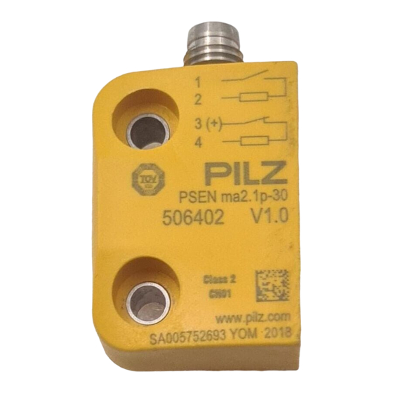
- Page 1 PSEN ma2.1p-10/-30 PSEN sensor technology Operating Manual-1004283-EN-03...
- Page 2 Preface This document is a translation of the original document. All rights to this documentation are reserved by Pilz GmbH & Co. KG. Copies may be made for internal purposes. Suggestions and comments for improving this documentation will be gratefully received.
-
Page 3: Table Of Contents
Contents Introduction Validity of documentation Using the documentation Definition of symbols Safety Intended use Safety regulations Safety assessment Use of qualified personnel Warranty and liability Disposal For your safety Unit features Function description Block diagram Operating distances Lateral and vertical offset Wiring Pin assignment Requirements and connection to evaluation devices... -
Page 4: Introduction
PSEN ma2.1p-10/-30 Introduction Validity of documentation This documentation is valid for the product PSEN ma2.1p-10/-30. It is valid until new docu- mentation is published. This operating manual explains the function and operation, describes the installation and provides guidelines on how to connect the product. Using the documentation This document is intended for instruction. -
Page 5: Safety
PSEN ma2.1p-10/-30 INFORMATION This gives advice on applications and provides information on special fea- tures. Safety Intended use The safety function of the safety switch is: Safe detection of the magnetic actuator within the response range The safety switch meets the requirements in accordance with: EN 60947-5-3: PDDB only in connection –... -
Page 6: Safety Regulations
PSEN ma2.1p-10/-30 Safety regulations Safety assessment Before using a unit it is necessary to perform a safety assessment in accordance with the Machinery Directive. Functional safety is guaranteed for the product as a single component. However, this does not guarantee the functional safety of the overall plant/machine. In order to achieve the re- quired safety level for the overall plant/machine, define the safety requirements for the plant/machine and then define how these must be implemented from a technical and organ- isational standpoint. -
Page 7: For Your Safety
PSEN ma2.1p-10/-30 For your safety WARNING! Loss of safety function due to manipulation of the interlocking device Manipulation of the interlocking device may lead to serious injury and death. – You should prevent any possibility of the interlocking device being manipulated through the use of a spare actuator. -
Page 8: Block Diagram
PSEN ma2.1p-10/-30 Block diagram Actuator Safety switch Magnet Operating distances (mm) omin Legend Assured operating distance Min. operating distance omin Assured release distance The offset-independent values for the switching distances are included in the Technical details [ 15]. Operating Manual PSEN ma2.1p-10/-30 1004283-EN-03... -
Page 9: Lateral And Vertical Offset
Assured operating distance S in mm Lateral offset Vertical offset The stated values are valid at a temperature of 20 °C. Safety switch PSEN ma2.1p-30 Assured operating distance S in mm Lateral offset Vertical offset The stated values are valid at a temperature of 20 °C. -
Page 10: Wiring
For use of PSEN ma2.1p-10/-30 in accordance with DIN EN 60947-5-3 an evaluation device must be connected. Connect the PSEN ma2.1p-10/-30 either with a certified Pilz evaluation device or with an evaluation device with defined properties Certified Pilz evaluation devices are, for example: PNOZelog for safety gate monitoring –... - Page 11 PSEN ma2.1p-10/-30 – PNOZ e5.13p PNOZmulti for safety gate monitoring Configure the switch in the PNOZmulti Configurator with switch type 2. PSS for safety gate monitoring with standard function block SB064, SB066 or FS_Safety Gate PSSuniversal PLC for safety gate monitoring with function block FS_SafetyGate The correct connection to the respective evaluation device is described in the operating manual for the evaluation device.
- Page 12 PSEN ma2.1p-10/-30 +24 V Evaluation device +24 V Input circuit I0.0 PSEN i1 I0.1 I0.2 I0.3 Input circuit 23 24 33 34 43 44 11 12 21 22 31 32 41 11 12 21 22 33 34 43 44 PSENmag Fig.: Dual-channel connection of four PSENmag to the input circuits of an evaluation device Operating Manual PSEN ma2.1p-10/-30 1004283-EN-03...
-
Page 13: Installation
PSEN ma2.1p-10/-30 Examples for connection to Pilz evaluation devices: PNOZmulti PSENmag PSEN i1 brown white blue black Legend I0 Input OSSD I1 Input OSSD T1, T2 Test pulse outputs Installation CAUTION! Potential loss of safety function due to changed device properties The unit's properties may be affected if installed in an environment contain- ing electrically or magnetically conductive material. -
Page 14: Adjustment
The protection type (see Technical details [ 15]) can only be achieved by using the Pilz connection leads available as an accessory. Adjustment The safety switch may only be used with the corresponding actuator PSEN 2.1-10. Always test the function with series connections with the PSEN i1 interface and connec- ted evaluation device. -
Page 15: Periodic Test
PSEN ma2.1p-10/-30 The stated operating distances (see Technical details [ 15]) only apply when the safety switch and actuator are installed according to the specifications Installation [ 13]. Operating distances may deviate if other arrangements are used. Note the maximum permitted lateral and vertical offset (see Operating distances and Lateral and vertical offset [ 8]). - Page 16 PSEN ma2.1p-10/-30 Electrical data 506405 506407 Supply voltage Voltage 24 V 24 V Kind Voltage tolerance -20 %/+20 % -20 %/+20 % Supply voltage Max. current 10 mA 10 mA Max. switching frequency 10 Hz 10 Hz Lowest operating current (Im) 1 mA 1 mA Switching voltage...
-
Page 17: Safety Characteristic Data
PSEN ma2.1p-10/-30 Mechanical data 506405 506407 Operating distances Assured operating distance Sao 3 mm 6 mm Min. operating distance Somin 0,5 mm 0,5 mm Typical operating distance So 4,5 mm 8 mm Assured release distance Sar 19 mm 25 mm Typical release distance Sr 6,5 mm 10 mm... -
Page 18: Order Reference
Order no. PSEN ma2.1p-10/ Magnetic safety switch, actu- 4-pin M8 male connector 506 405 PSEN2.1-10/3mm/1unit ator, assured operating dis- tance 3 mm PSEN ma2.1p-30/ Magnetic safety switch, actu- 4-pin M8 male connector 506 407 PSEN2.1-10/6mm/1unit ator, assured operating dis- tance 6 mm PSEN... -
Page 19: Ec Declaration Of Conformity
European Parliament and of the Council. The complete EC Declaration of Conformity is available on the Internet at www.pilz.com/downloads. Representative: Norbert Fröhlich, Pilz GmbH & Co. KG, Felix-Wankel-Str. 2, 73760 Ost- fildern, Germany Operating Manual PSEN ma2.1p-10/-30... - Page 20 Back cover Support Technical support is available from Pilz round the clock. Americas Australia Scandinavia Brazil +61 3 95600621 +45 74436332 +55 11 97569-2804 Spain Canada Europe +34 938497433 +1 888-315-PILZ (315-7459) Austria Switzerland Mexico +43 1 7986263-0 +41 62 88979-30...
Need help?
Do you have a question about the PSEN ma2.1p-30 and is the answer not in the manual?
Questions and answers