Table of Contents
Advertisement
Advertisement
Table of Contents

Related Manuals for Pilz PSEN ma1.4p-50


Summary of Contents for Pilz PSEN ma1.4p-50
- Page 1 PSEN ma1.4p-50 PSEN sensor technology Operating Manual-22126-EN-06...
- Page 2 Preface This document is the original document. All rights to this documentation are reserved by Pilz GmbH & Co. KG. Copies may be made for the user's internal purposes. Suggestions and comments for improving this documenta- tion will be gratefully received.
-
Page 3: Table Of Contents
..........................Installation type 1........................Installation type 2........................Adjustment ..........................Periodic test ........................... Dimensions in mm ......................... Technical details ........................Safety characteristic data ......................Order reference ........................System ............................Accessories ..........................EC declaration of conformity ....................Operating Manual PSEN ma1.4p-50 22126-EN-06... -
Page 4: Introduction
PSEN ma1.4p-50 Introduction Validity of documentation This documentation is valid for the product PSEN ma1.4p-50. It is valid until new document- ation is published. This operating manual explains the function and operation, describes the installation and provides guidelines on how to connect the product. -
Page 5: Safety
EN ISO 13849 and EN 62061. However, this does not guarantee the functional safety of the overall plant/machine. To achieve the relevant safety level of the overall plant/ machine’s required safety functions, each safety function needs to be considered separ- ately. Operating Manual PSEN ma1.4p-50 22126-EN-06... -
Page 6: Use Of Qualified Personnel
– If spare actuators are used, these must be installed as described in Installation [ 12]. – If the original actuators are replaced with substitute actuators, the ori- ginal actuators must be destroyed before disposal. Operating Manual PSEN ma1.4p-50 22126-EN-06... -
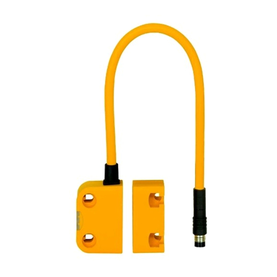
Page 7: Unit Features
If the actuator is within the response range (safety gate closed), the safety contacts of the safety switch are closed. Operate the PSEN ma1.4p-50 in conjunction with the following components: Actuator PSEN ma1.4-03 or actuator PSEN ma1.4-10 (see Order reference [... -
Page 8: Operating Distances
Lateral and vertical offset Legend [1] Lateral offset [2] Vertical offset Actuator PSEN ma1.4-03 Assured operating distance S in mm Lateral offset Vertical offset The stated values are valid at a temperature of 20 °C. Operating Manual PSEN ma1.4p-50 22126-EN-06... -
Page 9: Wiring
Pin assignment NOTICE The colour marking for the connection lead only applies for the cable that Pilz supplies as an accessory The safety switch is shown in an unoperated condition. Operating Manual PSEN ma1.4p-50 22126-EN-06... -
Page 10: Requirements And Connection To Evaluation Devices
Requirements and connection to evaluation devices For use of PSEN ma1.4p-50 in accordance with DIN EN 60947-5-3 an evaluation device must be connected. Connect the PSEN ma1.4p-50 either with a certified Pilz evaluation device or with an evaluation device with defined properties... - Page 11 [ of PSEN ma1.4p-50 – Always comply with the max. switching current safety contacts of PSEN ma1.4p-50. Outputs at the evaluation device must only be switched on again when both reed con- tacts at the safety switch have been opened and closed (partial operation lock)
-
Page 12: Installation
Safety switches and actuators must be positioned so that they are secured against a change of position. The safety switch and actuator should only be secured using screws and nuts made of non-magnetic material (e.g. brass or stainless steel). Operating Manual PSEN ma1.4p-50 | 12 22126-EN-06... -
Page 13: Installation Type 1
6. Align sensor and tighten screws with max. 0,8 Nm. 7. Align actuator and tighten screws with max. 0,8 Nm. 8. Close used mounting holes using seal (1) or (4) (see Diagram [ 14]). Operating Manual PSEN ma1.4p-50 | 13 22126-EN-06... - Page 14 10. Close mounting holes on the sensing face using seal (3) (see Diagram [ 14]). 11. Installation of sensor and actuator is now complete. INFORMATION Seals (1), (2), (3) meet the requirements of UL 94 V0, seal (4) does not meet UL requirements. Operating Manual PSEN ma1.4p-50 | 14 22126-EN-06...
-
Page 15: Installation Type 2
6. Close mounting holes on the sensing face using seal (3) (see Diagram [ 15]). 7. Installation of sensor and actuator is now complete. INFORMATION Seals (1), (2), (3) meet the requirements of UL 94 V0, seal (4) does not meet UL requirements. Operating Manual PSEN ma1.4p-50 | 15 22126-EN-06... -
Page 16: Adjustment
Carry out a monthly function test on the safety switch and actuator. Always test the function with a connected evaluation device. The safety function may only be checked by qualified personnel. Dimensions in mm 14,4 14,4 26,4 Operating Manual PSEN ma1.4p-50 | 16 22126-EN-06... -
Page 17: Technical Details
Frequency 10 - 55 Hz 10 - 55 Hz Amplitude 1 mm 1 mm Shock stress Acceleration Duration 11 ms 11 ms Airgap creepage Pollution degree Rated insulation voltage 25 V 25 V Operating Manual PSEN ma1.4p-50 | 17 22126-EN-06... - Page 18 Where standards are undated, the 2015-09 latest editions shall apply. Use with ambient temperatures between -28 °C and -10 °C When using the actuator PSENma1.4-10 please note the reduced assured operating dis- tance of 7 mm with a minimum ambient temperature of -28 °C. Operating Manual PSEN ma1.4p-50 | 18 22126-EN-06...
-
Page 19: Safety Characteristic Data
Magnetic safety switch 4-pin M8 male connector 506 308 1switch PSEN ma1.4-03mm Actuator with assured operat- 506 300 1actuator ing distance 3 mm PSEN ma1.4-10mm Actuator with assured operat- 506 301 1actuator ing distance 10 mm Operating Manual PSEN ma1.4p-50 | 19 22126-EN-06... -
Page 20: Accessories
European Parliament and of the Council. The complete EC Declaration of Conformity is available on the Internet at www.pilz.com/downloads. Authorised representative: Norbert Fröhlich, Pilz GmbH & Co. KG, Felix-Wankel-Str. 2, 73760 Ostfildern, Germany Operating Manual PSEN ma1.4p-50... - Page 21 We are represented internationally. Please refer to our homepage www.pilz.com for further details or contact our headquarters. Headquarters: Pilz GmbH & Co. KG, Felix-Wankel-Straße 2, 73760 Ostfildern, Germany Telephone: +49 711 3409-0, Telefax: +49 711 3409-133, E-Mail: info@pilz.com, Internet: www.pilz.com...
Need help?
Do you have a question about the PSEN ma1.4p-50 and is the answer not in the manual?
Questions and answers