Advertisement
Quick Links
22 121-03
PSEN ma1.4a-51
PSEN ma1.4a-51
22 121-03
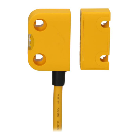
Sicherheitsschalter PSEN ma1.4a-51
Der Sicherheitsschalter erfüllt Forderungen der
833339787
EN 60204-1.
Der Sicherheitsschalter erfüllt EN 60947-5-3
nur zusammen mit dem Betätiger
PSEN ma1.4-03mm oder PSEN ma1.4-10mm
und hierfür zugelassenen Auswertegeräten.
Schließen Sie den Sicherheitsschalter nur an
Auswertegeräte an, die im Abschnitt "An-
schlüsse" aufgeführt sind.
Zu ihrer Sicherheit
Installieren und nehmen Sie das Gerät nur
547263243
dann in Betrieb, wenn Sie diese Betriebsan-
leitung gelesen und verstanden haben und
Sie mit den geltenden Vorschriften über Ar-
beitssicherheit und Unfallverhütung vertraut
sind.
Beachten Sie die VDE- sowie die örtlichen
Vorschriften, insbesondere hinsichtlich
Schutzmaßnahmen
Durch Öffnen des Gehäuses oder eigen-
mächtige Umbauten erlischt jegliche Ge-
währleistung.
Gerätemerkmale
1091646731
Zum Sicherheitsschalter gehört der Betätiger
PSEN ma1.4-03mm oder PSEN ma1.4-
10mm
1091650443
Sicherheitsschalter mit Kabel (5 m)
510237579
2 Sicherheitskontakte (Schließer)
1091653387
1 Hilfskontakt (Schließer)
1091670795
Betätiger PSEN ma1.4-03mm:
– Gesicherter Schaltabstand: 3 mm
– Gesicherter Ausschaltabstand: 12 mm
Betätiger PSEN ma1.4-10mm:
– Gesicherter Schaltabstand: 10 mm
– Gesicherter Ausschaltabstand: 22 mm
eckige Bauform
510316939
Wirkweise magnetisch
510321547
Schaltspannung 24 V DC
510477451
LED zur Anzeige des Schaltzustands
763865611
Safety switch PSEN ma1.4a-51
The safety switch meets the requirements of
EN 60204-1.
The safety switch only complies with
EN 60947-5-3 in conjunction with the actuator
PSEN ma1.4-03mm or PSEN ma1.4-10mm
and its approved evaluation devices.
The safety switch should only be connected to
the evaluation devices listed under "Connec-
tions".
For your safety
Only install and commission the unit if you
have read and understood these operating
instructions and are familiar with the applica-
ble regulations for health and safety at work
and accident prevention.
Ensure VDE and local regulations are met,
especially those relating to safety.
Any guarantee is rendered invalid if the hous-
ing is opened or unauthorised modifications
are carried out.
Unit features
The safety switch is used with the actuator
PSEN ma1.4-03mm or PSEN ma1.4-10mm
Safety switch with cable (5 m)
2 safety contacts (N/O)
1 auxiliary contact (N/O)
Actuator PSEN ma1.4-03mm:
– Assured operating distance: 3 mm
– Assured release distance: 12 mm
Actuator PSEN ma1.4-10mm:
– Assured operating distance: 10 mm
– Assured release distance: 22 mm
Square design
Works magnetically
Switching voltage 24 VDC
LED to display switch status
- 1 -
Capteur de sécurité PSEN ma1.4a-51
Le capteur de sécurité satisfait aux exigences
de l'EN 60204-1.
Le capteur de sécurité est conforme à la norme
EN 60947-5-3 uniquement lorsqu'il est utilisé
avec l'actionneur PSEN ma1.4-03mm ou
PSEN ma1.4-10mm et les unités de contrôle
spécialement homologuées.
Ne raccordez le capteur de sécurité qu'aux uni-
tés de contrôle indiquées dans le chapitre
« Raccordements ».
Pour votre sécurité
Vous n'installerez l'appareil et ne le mettrez
en service qu'après avoir lu et compris le
présent manuel d'utilisation et vous être fa-
miliarisé avec les prescriptions en vigueur
sur la sécurité du travail et la prévention des
accidents.
Respectez les normes locales ou VDE, parti-
culièrement en ce qui concerne la sécurité.
L'ouverture de l'appareil ou sa modification
annule automatiquement la garantie.
Caractéristiques de l'appareil
L'actionneur PSEN ma1.4-03mm ou
PSEN ma1.4-10mm est associé au capteur
de sécurité.
Capteur de sécurité avec câble (5 m)
2 contacts de sécurité (contacts à fermeture)
1 contact d'information (contact à fermeture)
Actionneur PSEN ma1.4-03mm :
– Distance de commutation de sécurité :
3 mm
– Distance de déclenchement de
sécurité : 12 mm
Actionneur PSEN ma1.4-10mm :
– Distance de commutation de sécurité :
10 mm
– Distance de déclenchement de
sécurité : 22 mm
architecture rectangulaire
actionnement magnétique
tension commutée 24 V DC
LED pour l'affichage de l'état de commuta-
tion
Advertisement

Related Manuals for Pilz PSEN ma1.4a-51


Summary of Contents for Pilz PSEN ma1.4a-51
- Page 1 PSEN ma1.4a-51 22 121-03 PSEN ma1.4a-51 Sicherheitsschalter PSEN ma1.4a-51 Safety switch PSEN ma1.4a-51 Capteur de sécurité PSEN ma1.4a-51 833339787 Der Sicherheitsschalter erfüllt Forderungen der The safety switch meets the requirements of Le capteur de sécurité satisfait aux exigences EN 60204-1.
- Page 2 Schaltabstände Operating distances Distances de commutation Legende Légende 1091685643 : Seitenversatz : Lateral offset : Décalage latéral : Höhenversatz : Vertical offset : Décalage en hauteur : Schaltzustände (y-Achse) in Abhängigkeit : Switch statuses (y-axis) dependent on the : Etats de commutation (axe y) en fonction des Schaltabstands (x-Achse) operating distance (x-axis) de la distance de commutation (axe x)
- Page 3 Verdrahtung Wiring Câblage 492354955 Beachten Sie: Please note: Important : Angaben im Abschnitt „Technische Daten“ Information given in the “Technical details” Tenez compte impérativement des données unbedingt einhalten. must be followed. indiquées au chapitre "Caractéristiques Berechnung der max. Leitungslänge I Calculation of the max.
- Page 4 Anschluss an Auswertegeräte Connection to evaluation devices Raccordement aux unités de contrôle Anschluss an Meldeausgang mit LED Connection to signal output with LED Raccordement à la sortie d'information avec PNOZ X, PNOZsigma, PNOZelog PNOZmulti, PSS, PSSu Anschluss an PNOZ X, PNOZsigma, Connection to PNOZ X, PNOZsigma, Raccordement aux PNOZ X, PNOZsigma, PNOZelog...
- Page 5 Anschluss an PSS mit oder ohne Connection to PSS with or without Raccordement au PSS avec ou sans SafetyBUS p und PSSu SafetyBUS p and PSSu SafetyBUS p et PSSu 928691211 ACHTUNG! CAUTION! ATTENTION ! Die Sicherheitsschalter dürfen an einer PSS The safety switches may only be operated Les capteurs de sécurité...
- Page 6 Montage Variante 1 Installation type 1 Montage du modèle 1 1086268427 1. Gewinde (M4) in gewünschter Position 1. Cut the thread (M4) in the required posi- 1. Couper le filetage (M4) dans la position schneiden. tion. souhaitée. 2. Sensor mit einer Schraube fixieren. 2.
- Page 7 Montage Variante 2 Installation type 2 Montage du modèle 2 Montieren Sie den Sensor wie bei Montage Va- Install the sensor as shown for installation type Montez le capteur de la même manière que 1086273035 riante 1 pour le modèle 1 1.
- Page 8 Justage Adjustment Ajustement 1095251595 Prüfen Sie die Funktion immer mit einem der Always test the function with one of the ap- Vérifiez la fonction uniquement avec l'un des zugelassenen Auswertegeräte. proved evaluation devices. appareils de contrôle homologués. Bei unbetätigten Reedkontakten leuchtet die The LED lights when the reed contacts are La LED s'allume lorsque les contacts Reed LED (Schutzeinrichtung geöffnet oder Si-...
- Page 9 Bevollmächtigter: Norbert Fröhlich, Authorised representative: Norbert Fröhlich, Représentant : Norbert Fröhlich, Pilz GmbH & Co. KG, Felix-Wankel-Str. 2, Pilz GmbH & Co. KG, Felix-Wankel-Str. 2, Pilz GmbH & Co. KG, Felix-Wankel-Str. 2, 73760 Ostfildern, Deutschland...
- Page 10 22 121-03 2009-12 Printed in Germany...
Need help?
Do you have a question about the PSEN ma1.4a-51 and is the answer not in the manual?
Questions and answers