Table of Contents
Advertisement
Quick Links
Advertisement
Table of Contents
Troubleshooting

Subscribe to Our Youtube Channel
Related Manuals for Supermicro SuperServer ARS-210M-NR


Summary of Contents for Supermicro SuperServer ARS-210M-NR
- Page 1 SuperServer ® ARS-210M-NR USER’S MANUAL Revision 1.0...
- Page 2 State of California, USA. The State of California, County of Santa Clara shall be the exclusive venue for the resolution of any such disputes. Supermicro's total liability for all claims will not exceed the price paid for the hardware product.
- Page 3 If you have any questions, please contact our support team at: support@supermicro.com This manual may be periodically updated without notice. Please check the Supermicro website for possible updates to the manual revision level. Secure Data Deletion A secure data deletion tool designed to fully erase all data from storage devices can be found on our website: https://www.supermicro.com/about/policies/disclaimer.cfm?url=/wdl/utility/...
-
Page 4: Table Of Contents
Preface Contents Contacting Supermicro ......................8 Chapter 1 Introduction 1.1 Overview ..........................9 1.2 System Features ........................10 Front View .........................10 Control Panel .........................12 Rear View ..........................13 1.3 System Architecture ......................14 Main Components ......................14 System Block Diagram ......................15 1.4 Motherboard Layout ......................16 Quick Reference Table ......................17 Chapter 2 Server Installation 2.1 Overview ..........................19... - Page 5 Preface Chapter 3 Maintenance and Component Installation 3.1 Removing Power .......................28 3.2 Accessing the System ......................29 3.3 Static-Sensitive Devices .....................30 Precautions ........................30 Unpacking .........................30 3.4 Processor and Heatsink Installation ...................31 The Ampere Altra/Altra Max Processor ................31 Overview of the Processor Socket ..................32 Overview of the Heatsink ....................32 Installing the Processor .....................33 Installing the Heatsink .......................36...
- Page 6 Preface Chapter 4 Motherboard Connections 4.1 Power Connections ......................54 4.2 Headers and Connectors ....................56 Front Control Panel .......................59 Front Panel Header .......................62 4.3 Input/Output Ports ......................65 4.4 Jumpers ..........................68 Explanation of Jumpers.....................68 4.5 LED Indicators ........................70 Chapter 5 Software 5.1 Ubuntu OS Installation .......................72 5.2 BMC ............................72 5.3 Logging into the BMC (Baseboard Management Controller) ..........72 Chapter 6 Troubleshooting and Support...
- Page 7 Appendix A Standardized Warning Statements for AC Systems Appendix B System Specifications BSMI ............................109 Appendix C Updating Firmware with Supermicro Update Manager C.1 Overview ........................... 111 C.2 Updating Firmware with SUM in-band ................112 C.3 Updating Firmware with SUM out-of-band ...............113 Appendix D Updating BIOS and BMC with OpenBMC WebGUI D.1 Overview ...........................115...
-
Page 8: Contacting Supermicro
San Jose, CA 95131 U.S.A. Tel: +1 (408) 503-8000 Fax: +1 (408) 503-8008 Email: marketing@supermicro.com (General Information) Sales-USA@supermicro.com (Sales Inquiries) Government_Sales-USA@supermicro.com (Gov. Sales Inquiries) support@supermicro.com (Technical Support) RMA@supermicro.com (RMA Support) Webmaster@supermicro.com (Webmaster) Website: www.supermicro.com Europe Address: Super Micro Computer B.V. -
Page 9: Chapter 1 Introduction
2U Rackmount 3.5 x 17.2 x 25.5 in. / 89 x 437 x 648 mm (H x W x D) Notes: A Quick Reference Guide can be found on the product page of the Supermicro website. The following safety models associated with the ARS-210M-NR have been certified... -
Page 10: System Features
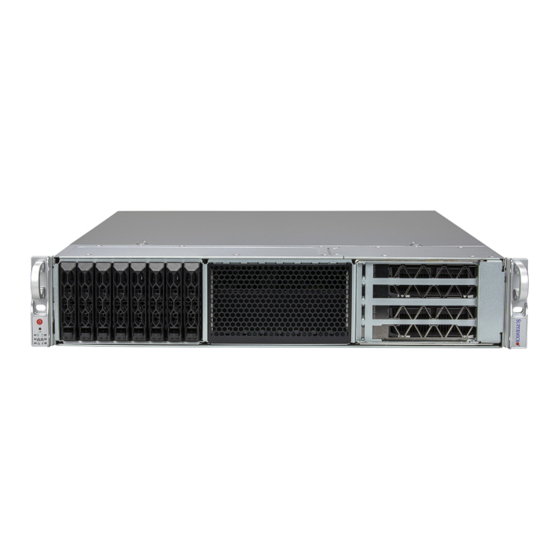
Chapter 1: Introduction 1.2 System Features The following views of the system display the main features. Refer to Appendix B for additional specifications. Front View The illustration below includes up to 8/16/24 storage drvies, a control panel, or four PCIe slots. PCIe Slots Storage Drives Control Panel... - Page 11 Chapter 1: Introduction Storage Drives Figure 1-5. Front View (12 Bays Optional) System Features: Front Feature Description Four 2.5" NVMe + four DW GPUs (Default) 16 drives, four 2.5" NVMe / SAS / SATA + twelve 2.5" SAS / SATA + four DW GPUs (Optional) Storage Drives Twenty-four 2.5"...
-
Page 12: Control Panel
Chapter 1: Introduction Control Panel Power Button UID Button Power LED Drive Activity LED NIC2 LED NIC1 LED Power Fail LED Information LED Figure 1-6. Control Panel Control Panel Features Feature Description The main power switch applies or removes primary power from the power supply to the Power button server but maintains standby power. -
Page 13: Rear View
Chapter 1: Introduction Rear View The illustration below shows the features on the rear of the chassis. PCIe Slots (FH) PWS2 Micro USB IPMI LAN Ports (2) PCIe Slots (LP) PWS1 AIOM Port Port USB 3.0 Ports (2) Figure 1-7. System: Rear View System Features: Rear Feature Description... -
Page 14: System Architecture
Chapter 1: Introduction 1.3 System Architecture This section covers the locations of the system's main components, a system block diagram, and a motherboard layout with the connectors and jumpers called out. Main Components Power Supply Modules DIMM Slots Fans PCIe (FH) Four Drive Bays Figure 1-8. -
Page 15: System Block Diagram
Chapter 1: Introduction System Block Diagram The block diagram below shows the connections and relationships between the subsystems and major components of the overall system. DDR4 3200 2DPC Channel 4 Channel 0 DDR4 3200 2DPC AMPERE Processor DDR4 3200 2DPC DDR4 3200 2DPC Channel 5 Channel 1... -
Page 16: Motherboard Layout
Chapter 1: Introduction 1.4 Motherboard Layout Below is a layout of the R12SPD-A/-R motherboard with a jumper, connector, and LED locations shown. See the table on the following page for descriptions. For detailed descriptions, pinout information, and jumper settings, refer to Chapter 4 or the Motherboard... -
Page 17: Quick Reference Table
Chapter 1: Introduction Quick Reference Table Jumper Description Default Setting CPU UART/BMC Debug Pins 1-2 Closed (CPU UART) JPL1 LAN1/2 Enable/Disable Pins 1-2 (Enabled) Description Status LED1 Unit Identifier LED Solid Blue: Unit Identified LED2 Power LED Solid Green: Power On LED3 System Status LED Solid Red: CPU Fault... - Page 18 Chapter 1: Introduction Connector Connector USB0/1 Front-Accessible USB 2.0 Header USB2/3 USB 3.0 Type-A Ports on the Rear I/O Panel USB4/5 Front-Accessible USB 3.0 Header VGA Port...
-
Page 19: Chapter 2 Server Installation
Chapter 2: Server Installation Chapter 2 Server Installation 2.1 Overview This chapter provides advice and instructions for mounting your system in a server rack. If your system is not already fully integrated with processors, system memory, etc., refer to Chapter 3 for details on installing those specific components. -
Page 20: Rack Precautions
Chapter 2: Server Installation Rack Precautions • Ensure that the leveling jacks on the bottom of the rack are extended to the floor so that the full weight of the rack rests on them. • In single rack installations, stabilizers should be attached to the rack. In multiple rack in- stallations, the racks should be coupled together. -
Page 21: Mechanical Loading
Chapter 2: Server Installation Mechanical Loading Equipment should be mounted into a rack so that a hazardous condition does not arise due to uneven mechanical loading. Circuit Overloading Consideration should be given to the connection of the equipment to the power supply circuitry and the effect that any possible overloading of circuits might have on overcurrent protection and power supply wiring. -
Page 22: Installing The Rails
Chapter 2: Server Installation 2.4 Installing the Rails This section provides information on installing the chassis into a rack unit with the rails provided. There are a variety of rack units on the market, which may mean that the assembly procedure will differ slightly from the instructions provided. -
Page 23: Releasing The Inner Rail
Chapter 2: Server Installation Releasing the Inner Rail Each inner rail has a locking latch. This latch prevents the chassis from coming completely out of the rack when the chassis is pulled out for servicing. To mount the rail onto the chassis, first release the inner rail from the outer rails. 1. -
Page 24: Installing The Inner Rails
Chapter 2: Server Installation Installing the Inner Rails Begin the rack mounting procedure by installing the inner rails to the chassis. 1. Identify the left and right inner rails. They are labeled. 2. Place the inner rail firmly against the side of the chassis, aligning the hooks in the chassis with the inner rail's. -
Page 25: Installing The Outer Rails Onto The Rack
Chapter 2: Server Installation Installing the Outer Rails onto the Rack 1. Press upward on the locking tab at the rear end of the middle rail. 2. Push the middle rail back into the outer rail. 3. Hang the hooks on the front of the outer rail onto the square holes on the front of the rack. -
Page 26: Installing The Chassis Into A Rack
Chapter 2: Server Installation 2.5 Installing the Chassis into a Rack Once rails are attached to the chassis and the rack, you can install the server. 1. Pull the middle rail out of the front of the outer rail and make sure that the ball bearing shuttle is locked at the front of the middle rail. -
Page 27: Removing The Chassis From The Rack
Chapter 2: Server Installation Removing the Chassis from the Rack Caution! It is dangerous for a single person to off-load the heavy chassis from the rack without assistance. Be sure to have sufficient assistance supporting the chassis when removing it from the rack. -
Page 28: Chapter 3 Maintenance And Component Installation
Chapter 3: Maintenance and Component Installation Chapter 3 Maintenance and Component Installation This chapter provides instructions on installing and replacing main system components. To prevent compatibility issues, only use components that match the specifications and/or part numbers given. Installation or replacement of most components requires that power first be removed from the system. -
Page 29: Accessing The System
Chapter 3: Maintenance and Component Installation 3.2 Accessing the System The CSE-LB26TS-R2K08P chassis features a removable top cover, which allows easy access to the inside of the chassis. Removing the Top Cover 1. Remove the screw on each side of the chassis. 2. -
Page 30: Static-Sensitive Devices
Chapter 3: Maintenance and Component Installation 3.3 Static-Sensitive Devices Electrostatic Discharge (ESD) can damage electronic com ponents. To avoid damaging your motherboard, it is important to handle it very carefully. The following measures are generally sufficient to protect the system PCBs from ESD. Precautions •... -
Page 31: Processor And Heatsink Installation
(gold contacts). Improper installation or socket misalignment can cause serious damage to the processor or socket, which may require manufacturer repairs. • Refer to the Supermicro website for updates on processor support. • All graphics in this manual are for illustrations only. Your components may look different. -
Page 32: Overview Of The Processor Socket
Chapter 3: Maintenance and Component Installation Overview of the Processor Socket The processor socket is protected by a plastic protective cover. 1. Plastic Protective Cover 2. LGA 4926 Socket Overview of the Heatsink The heatsink is attached to the processor after the processor is secured in the LGA 4926 socket. -
Page 33: Installing The Processor
Chapter 3: Maintenance and Component Installation Installing the Processor 1. Use a screwdriver with a Torx T20 screw head bit to unscrew the socket force frame. Unscrew counterclockwise in the sequence 5-4-3-2-1. The screws are numbered on the socket force frame next to each screw hole. Screw #2 Screw #4 Screw #5... - Page 34 Chapter 3: Maintenance and Component Installation 3. When the socket force frame is open, remove the plastic protective cover from the socket. 4. When the plastic protective cover is removed from the socket, gently pick up the processor. Warning! The exposed socket contacts are extremely vulnerable and can be damaged easily. Do not touch or drop objects onto the contacts and be careful removing the PnP cover cap and when placing the rail frame over the socket.
- Page 35 Chapter 3: Maintenance and Component Installation 5. Align the CPU pad cutout on the corner of the processor to the respective cutout on the LGA 4926 socket. 6. Re-screw the socket screws in the sequence 1-2-3-4-5. The socket force frame is spring loaded and has to be held in place.
-
Page 36: Installing The Heatsink
Chapter 3: Maintenance and Component Installation 7. When finished, the socket force frame will secure the processor. Installing the Heatsink 1. After the processor is secure, you must install the heatsink to the socket frame. Ensure a proper amount of thermal grease is applied to the heatsink. Lower the heatsink down until the four screws on the heatsink align with the four screw holes on the socket frame. - Page 37 Chapter 3: Maintenance and Component Installation 2. Starting with two screws on opposite corners, use a Phillips #1 screwdriver to press down and tighten the screws on the heatsink. 3. When finished, the heatsink will be secured over the socket and processor.
-
Page 38: Motherboard Installation
Chapter 3: Maintenance and Component Installation 3.5 Motherboard Installation All motherboards have standard mounting holes to fit different types of chassis. Make sure that the locations of all the mounting holes for both the motherboard and the chassis match. Although a chassis may have both plastic and metal mounting fasteners, metal ones are highly recommended because they ground the motherboard to the chassis. -
Page 39: Installing The Motherboard
Chapter 3: Maintenance and Component Installation Installing the Motherboard 1. Install the I/O shield into the back of the chassis, if applicable. 2. Locate the mounting holes on the motherboard. See the previous page for the location. 3. Locate the matching mounting holes on the chassis. Align the mounting holes on the motherboard against the mounting holes on the chassis. -
Page 40: Memory Support And Installation
Chapter 3: Maintenance and Component Installation 3.6 Memory Support and Installation Note: Check the Supermicro website for recommended memory modules. Important: Exercise extreme care when installing or removing memory modules to prevent any possible damage. Memory Support The R12SPD-A/-R motherboard supports up to 4 TB of DDR4 ECC and Non-ECC UDIMM/ LRDIMM/RDIMM/3DS RDIMM memory with speeds of up to 3200 MT/s in 16 memory slots. -
Page 41: General Guidlines For Optimizing Memory Performance
Chapter 3: Maintenance and Component Installation General Guidlines for Optimizing Memory Performance • Insert the desired number of DIMMs into the memory slots based on the memory population sequences. • It's recommended to use DDR4 memory of the same type, size, and speed. •... -
Page 42: Dimm Installation
Chapter 3: Maintenance and Component Installation DIMM Installation COM1 PRESS FIT PRESS FIT LED1 MH12 1. Insert DIMM modules in the order noted on AST2600 JPF1 USB2/3 IPMI_LAN JPL1 JMD1_SRW2 the preceding page. Locate DIMM memory LEDM1 MH13 22110 LAN2 LAN1 LED2 25G LAN... -
Page 43: Motherboard Battery
Chapter 3: Maintenance and Component Installation 3.7 Motherboard Battery Battery Removal To remove the onboard battery, follow the steps below: 1. Power off your system and unplug your power cable. 2. Locate the onboard battery as shown below. 3. Using a tool such as a pen or a small screwdriver, push the battery lock outwards to unlock it. -
Page 44: Storage Drives
The CSE-LB26TS-R2K08P chassis supports up to sixteen 2.5" storage drives in drive carriers to simplify their removal from the chassis. These carriers also help promote proper airflow. Note: Enterprise level storage drives are recommended for use in Supermicro chassis and servers. - Page 45 Chapter 3: Maintenance and Component Installation Removing Drive Carriers from the Chassis 1. Push the release button on the drive carrier. This releases and extends the drive carrier handle. 2. Use the handle to pull the carrier out of the chassis as shown below. Caution: Except for short periods of time (swapping drives), do not operate the server with the drive carriers removed from the bays, regardless of how many drives are installed, for proper airflow.
- Page 46 Chapter 3: Maintenance and Component Installation Installing a Tooless 2.5" Storage Drive 1. Place the empty storage drive carrier on a flat surface. 2. Retract the blue clips on the side of the carrier. 3. Insert a 2.5" storage drive at an angle into the carrier so that the mounting screw holes on the right side of the drive align with two stubs in the drive carrier.
-
Page 47: Installing Expansion Cards
Chapter 3: Maintenance and Component Installation Installing Expansion Cards The system can accommodate two low-profile and up to eight full length, full height PCIe cards. Installing a low-profile Expansion Card 1. Power down the system and remove the cover. 2. In the rear of the chassis, remove the blank PCIe slot assembly as shown. 3. - Page 48 Chapter 3: Maintenance and Component Installation Installing a GPU Expansion Card (Rear of Chassis) 1. Power down the system and remove the cover. 2. In the rear of the chassis, remove the blank PCIe slot GPU bracket assemblies as shown. Figure 3-5.
- Page 49 Chapter 3: Maintenance and Component Installation 3. Remove the GPU brace from the GPU bracket assembly by loosening the screw that is holding down the GPU brace. Loosen Screw GPU Bracket Assembly Loosen Screw GPU Bracket Assembly GPU Brace GPU Brace 4.
- Page 50 Chapter 3: Maintenance and Component Installation Installing a GPU Expansion Card (Front of Chassis) 1. Power down the system and remove the cover. 2. In the front of the chassis, remove the blank PCIe slot GPU bracket assembly by first removing the four screws at the bottom of the chassis, as shown below.
-
Page 51: System Cooling
Chapter 3: Maintenance and Component Installation 3.9 System Cooling System Fans There are four hot-swap fans that provide cooling. Each fan can be replaced without powering down the system. Fan speed is controlled by a system temperature setting in IPMI. If a fan fails, the remaining fans will ramp up to full speed. -
Page 52: Air Shrouds
Chapter 3: Maintenance and Component Installation Air Shrouds An air shroud concentrates airflow to maximize fan efficiency. It covers the processors and heatsinks. Installing the Air Shroud The air shroud fits on top of the motherboard. It has two layers, the top and the bottom. Align the pins and press the bottom plastic air shroud into the chassis along the edges.Then, press down the top air shroud into the bottom shroud, and push it forward. -
Page 53: Power Supply
The system features two redundant power supply modules. The power modules can be changed without powering down the system. New units can be ordered directly from Supermicro or authorized distributors. These power supplies are auto-switching capable and enable them to automatically sense the input voltage and operate at a 100-120 V or 180-240 V. -
Page 54: Chapter 4 Motherboard Connections
Chapter 4: Motherboard Connections Chapter 4 Motherboard Connections This section describes the connections on the motherboard and provides pinout definitions. Note that depending on how the system is configured, not all connections are required. The LEDs on the motherboard are also described here. A motherboard layout indicating component locations may be found in Chapter 1. - Page 55 Chapter 4: Motherboard Connections 5V/12V Power Connector for Special Riser Cards JPWR4 is a 5 V/12 V 4-pin power connector for riser cards. Special Riser Card Power Pin Definitions Pin# Definition Ground Ground +12 V +5 V ATX PSU 24-Pin Power Connector JPWR5 is a 24-pin power supply connector that meets the ATX SSI EPS 24-pin specification.
-
Page 56: Headers And Connectors
Chapter 4: Motherboard Connections 4.2 Headers and Connectors Fan Headers Six 4-pin fan headers on the motherboard. Although pins 1-3 of the fan headers are backward compatible with the traditional 3-pin fans, we recommend you use 4-pin fans to take advantage of the fan speed control via Pulse Width Modulation (PWM) through the thermal management. - Page 57 A Trusted Platform Module (TPM) 2.0 header is located at JTPM1 to provide TPM 2.0 support. Use this header to enhance system performance and data security. Refer to the table below for pin definitions. Go to the following link for more information on the TPM: https://www. supermicro.com/manuals/other/TPM.pdf. Trusted Platform Module Header Pin Definitions Pin#...
- Page 58 The motherboard features one Advanced I/O Module (AIOM) PCIe 4.0 x16 slot, which can connect additional LAN ports, VPU, storage devices, etc. to the motherboard. Visit the Supermicro website for all available module options. Power must be unplugged prior to removing or installing an AIOM module card.
-
Page 59: Front Control Panel
JF1 contains header pins for various buttons and indicators that are normally located on a control panel at the front of the chassis. These connectors are designed specifically for use with Supermicro chassis. See the figure below for the descriptions of the front control panel buttons and LED indicators. - Page 60 Chapter 4: Motherboard Connections Power Button The Power Button connection is located on pins 1 and 2 of JF1. Momentarily contacting both pins will power on/off the system. Refer to the table below for pin definitions. Power Button Pin Definitions (JF1) Pin# Definition Signal...
- Page 61 Chapter 4: Motherboard Connections NIC1/NIC2 (LAN1/LAN2) The Network Interface Controller (NIC) LED connection for LAN port 1 is located on pins 11 and 12 of JF1, and LAN port 2 is on pins 9 and 10. Attach the NIC LED cables here to display network activity.
-
Page 62: Front Panel Header
JFP1 contains header pins for various buttons and indicators that are normally located on a control panel at the front of the chassis. These connectors are designed specifically for use with Supermicro chassis. See the figure below for the descriptions of the front control panel buttons and LED indicators. - Page 63 Chapter 4: Motherboard Connections Power On & BMC/BIOS Status LED Button The Power On and BMC/BIOS Status LED button is located on pin 1 of JFP1. Power On and BMC/BIOS Status LED (JFP1) Status Definition Solid Green System power on BMC/BIOS blinking green at 4 Hz BMC/BIOS checking BIOS blinking green at 4 Hz...
- Page 64 Chapter 4: Motherboard Connections LAN1/LAN2 (MIC1/NIC2) The Network Interface Controller (NIC) LED connection for LAN port 1 is located on pin 6 of JFP1, and the NIC LED connection for LAN port 2 is located on pin 5 of JFP1. LAN1/LAN2 LED (JFP1) Status Definition...
-
Page 65: Input/Output Ports
Chapter 4: Motherboard Connections 4.3 Input/Output Ports See figures below for the locations and descriptions of the various I/O ports on the rear I/O panel of the motherboard. COM1 LED1 PRESS FIT PRESS FIT MH12 AST2600 JPF1 USB2/3 IPMI_LAN JPL1 JMD1_SRW2 LEDM1 MH13... - Page 66 Chapter 4: Motherboard Connections Dedicated IPMI LAN Port A dedicated IPMI LAN port is located on the rear I/O panel. IPMI LAN Pin Definitions Pin# Definition Pin# Definition Yellow LED- (Activity) Yellow LED+ (Activity) Amber LED+ (1 GbE Link) / Green LED- Green LED+ (100 MbE Link) / Amber LED+ VGA Port A video (VGA) port is located on the rear I/O panel near the IPMI LAN port.
- Page 67 The UID Indicator provides easy identification of a system unit that may be in need of service. Note: UID can also be triggered via IPMI on the motherboard. For more information on IPMI, refer to the IPMI User's Guide posted on our website at https://www.supermicro. com/support/ manuals/. UID Switch...
-
Page 68: Jumpers
Chapter 4: Motherboard Connections 4.4 Jumpers Explanation of Jumpers To modify the operation of the motherboard, jumpers are used to choose between optional settings. Jumpers create shorts between two pins to change the function associated with it. Pin 1 is identified with a square solder pad on the printed circuit board. See the motherboard layout page for jumper locations. - Page 69 Chapter 4: Motherboard Connections CPU UART/BMC Debug Change the setting of jumper J8 to switch the COM1 port function between CPU UART and BMC Debug. Set header J8 to CPU UART to allow the Micro USB COM port to read CPU UART per BMC.
-
Page 70: Led Indicators
Chapter 4: Motherboard Connections 4.5 LED Indicators CPU Fault LED LED3 is the system status LED for the motherboard. When power is detected, LED3 will indicate the status of the system. CPU Fault LED Color/State Definition Solid Red CPU Fault BMC Heartbeat LED LEDM1 is the BMC Heartbeat LED. - Page 71 Chapter 4: Motherboard Connections SFP28 LAN Status for LAN2 LED_L1 is two LEDs that indicate the status of LAN2. The top LED indicates link speed and the bottom LED indicates LAN2 port activity. SFP28 LAN Status for LAN1 Color/State Description Top LED Yellow 10 G Link...
-
Page 72: Chapter 5 Software
When logging in to the BMC for the first time, please use the unique password provided by Supermicro to log in. You can change the unique password to a user name and password of your choice for subsequent logins. -
Page 73: Chapter 6 Troubleshooting And Support
Chapter 6: Troubleshooting and Support Chapter 6 Troubleshooting and Support 6.1 Information Resources Website A great deal of information is available on the Supermicro website. Figure 6-1. Supermicro Website • Specifications for servers and other hardware are available by clicking Products. •... -
Page 74: Troubleshooting Procedures
Security Center for recent security notices Supermicro Phone and Addresses 6.2 Troubleshooting Procedures Use the following procedures to troubleshoot your system. If you have followed all of the procedures below and still need assistance, refer to the... -
Page 75: No Video
Chapter 6: Troubleshooting and Support No Video 1. If the power is on, but you have no video, remove all add-on cards and cables. 2. Use the speaker to determine if any beep codes are present. Refer to Appendix A details on beep codes. -
Page 76: Losing The System's Setup Configuration
Chapter 6: Troubleshooting and Support 4. Check for bad DIMM modules or slots by swapping a single module among all memory slots and check the results. Losing the System's Setup Configuration 1. Make sure that you are using a high-quality power supply. Always replace power supplies with the exact same model that came with the system. -
Page 77: Bios Error Beep (Post Codes)
Chapter 6: Troubleshooting and Support B. If the system becomes unstable before or during OS installation, check the following: 1. Source of installation: Make sure that the devices used for installation are working properly, including boot devices such as CD/Media drive. 2. -
Page 78: Additional Bios Post Codes
Before contacting Technical Support, please take the following steps. Also, note that as a motherboard manufacturer, Supermicro also sells motherboards through its channels, so it is best to first check with your distributor or reseller for troubleshooting services. They should know of any possible problems with the specific system configuration that was sold to you. -
Page 79: Frequently Asked Questions
Note: The SPI BIOS chip used on this motherboard cannot be removed. Send your motherboard back to our RMA Department at Supermicro for repair. For BIOS Recovery instructions, refer to the AMI BIOS Recovery Instructions posted at https://www.supermicro. -
Page 80: Uefi Bios Recovery
Warning: Do not upgrade the BIOS unless your system has a BIOS-related issue. Flashing the wrong BIOS can cause irreparable damage to the system. In no event shall Supermicro be liable for direct, indirect, special, incidental, or consequential damages arising from a BIOS update. - Page 81 USB flash or media device. Note 1: If you cannot locate the "Super.ROM" file in your drive disk, visit our website at www.supermicro.com to download the BIOS package. Extract the BIOS binary image into a USB flash device and rename it "Super.ROM" for the BIOS recovery use.
- Page 82 Chapter 6: Troubleshooting and Support 3. After locating the healthy BIOS binary image, the system will enter the BIOS Recovery menu as shown below. Note: At this point, you may decide if you want to start the BIOS recovery. If you decide to proceed with BIOS recovery, follow the procedures below.
- Page 83 Chapter 6: Troubleshooting and Support 5. After the BIOS recovery process is complete, press any key to reboot the system. 6. Using a different system, extract the BIOS package into a USB flash drive. 7. Press <Del> continuously during system boot to enter the BIOS Setup utility. From the top of the toolbar, select Boot to enter the submenu.
- Page 84 Chapter 6: Troubleshooting and Support 8. When the UEFI Shell prompt appears, type fs# to change the device directory path. Go to the directory that contains the BIOS package you extracted earlier from Step 6. Enter flash.nsh BIOSname.### at the prompt to start the BIOS update process. Note: Do not interrupt this process until the BIOS flashing is complete.
-
Page 85: Feedback
Chapter 6: Troubleshooting and Support 6.8 Feedback Supermicro values your feedback as we strive to improve our customer experience in all facets of our business. To provide feedback on our manuals, please email us at techwriterteam@ supermicro.com. -
Page 86: Contacting Supermicro
San Jose, CA 95131 U.S.A. Tel: +1 (408) 503-8000 Fax: +1 (408) 503-8008 Email: marketing@supermicro.com (General Information) Sales-USA@supermicro.com (Sales Inquiries) Government_Sales-USA@supermicro.com (Gov. Sales Inquiries) support@supermicro.com (Technical Support) RMA@supermicro.com (RMA Support) Webmaster@supermicro.com (Webmaster) Website: www.supermicro.com Europe Address: Super Micro Computer B.V. -
Page 87: Appendix A Standardized Warning Statements For Ac Systems
Supermicro's Technical Support department for assistance. Only certified technicians should attempt to install or configure components. Read this appendix in its entirety before installing or configuring components in the Supermicro chassis. These warnings may also be found on our website at http://www.supermicro.com/about/... - Page 88 Appendix A: Warning Statements Warnung WICHTIGE SICHERHEITSHINWEISE Dieses Warnsymbol bedeutet Gefahr. Sie befinden sich in einer Situation, die zu Verletzungen führen kann. Machen Sie sich vor der Arbeit mit Geräten mit den Gefahren elektrischer Schaltungen und den üblichen Verfahren zur Vorbeugung vor Unfällen vertraut. Suchen Sie mit der am Ende jeder Warnung angegebenen Anweisungsnummer nach der jeweiligen Übersetzung in den übersetzten Sicherheitshinweisen, die zusammen mit diesem Gerät ausgeliefert wurden.
- Page 89 Appendix A: Warning Statements . ٌ ا ك ً ف حالة و ٌ يك أى تتسبب ف اصابة جسذ ة ٌ هذا الزهز ع ٌ خطز !تحذ ز قبل أى تعول عىل أي هعذات،يك عىل علن بالوخاطز ال ا ٌجوة عي الذوائز ٍ...
- Page 90 Appendix A: Warning Statements Warnung Vor dem Anschließen des Systems an die Stromquelle die Installationsanweisungen lesen. ¡Advertencia! Lea las instrucciones de instalación antes de conectar el sistema a la red de alimentación. Attention Avant de brancher le système sur la source d'alimentation, consulter les directives d'installation. .יש...
- Page 91 Appendix A: Warning Statements Warnung Dieses Produkt ist darauf angewiesen, dass im Gebäude ein Kurzschluss- bzw. Überstromschutz installiert ist. Stellen Sie sicher, dass der Nennwert der Schutzvorrichtung nicht mehr als: 250 V, 20 A beträgt. ¡Advertencia! Este equipo utiliza el sistema de protección contra cortocircuitos (o sobrecorrientes) del edificio.
- Page 92 Appendix A: Warning Statements Power Disconnection Warning Warning! The system must be disconnected from all sources of power and the power cord removed from the power supply module(s) before accessing the chassis interior to install or remove system components (except for hot-swap components). 電源切断の警告...
- Page 93 Appendix A: Warning Statements אזהרה מפני ניתוק חשמלי !אזהרה יש לנתק את המערכת מכל מקורות החשמל ויש להסיר את כבל החשמלי מהספק .לפני גישה לחלק הפנימי של המארז לצורך התקנת או הסרת רכיבים يجب فصم اننظاو من جميع مصادر انطاقت وإ ز انت سهك انكهرباء من وحدة امداد انطاقت...
- Page 94 Appendix A: Warning Statements Attention Seul le personnel autorisé et le personnel de maintenance qualifié doivent être autorisés à installer, remplacer ou entretenir cet équipement.. !אזהרה .יש לאפשר רק צוות מורשה ואנשי שירות מוסמכים להתקין, להחליף או לטפל בציוד זה .ينبغي...
- Page 95 Appendix A: Warning Statements Warnung Diese Einheit ist zur Installation in Bereichen mit beschränktem Zutritt vorgesehen. Der Zutritt zu derartigen Bereichen ist nur mit einem Spezialwerkzeug, Schloss und Schlüssel oder einer sonstigen Sicherheitsvorkehrung möglich. ¡Advertencia! Esta unidad ha sido diseñada para instalación en áreas de acceso restringido. Sólo puede obtenerse acceso a una de estas áreas mediante la utilización de una herramienta especial, cerradura con llave u otro medio de seguridad.
- Page 96 Appendix A: Warning Statements Battery Handling Warning! There is the danger of explosion if the battery is replaced incorrectly. Replace the battery only with the same or equivalent type recommended by the manufacturer. Dispose of used batteries according to the manufacturer's instructions 電池の取り扱い...
- Page 97 Appendix A: Warning Statements هناك خطر من انفجار يف حالة اسحبذال البطارية بطريقة غري صحيحة فعليل اسحبذال البطارية فقط بنفس النىع أو ما يعادلها مام أوصث به الرشمة املصنعة جخلص من البطاريات املسحعملة وفقا لحعليامت الرشمة الصانعة 경고! 배터리가 올바르게 교체되지 않으면 폭발의 위험이 있습니다. 기존 배터리와 동일하거나 제 조사에서...
- Page 98 Appendix A: Warning Statements ¡Advertencia! Puede que esta unidad tenga más de una conexión para fuentes de alimentación. Para cortar por completo el suministro de energía, deben desconectarse todas las conexiones. Attention Cette unité peut avoir plus d'une connexion d'alimentation. Pour supprimer toute tension et tout courant électrique de l'unité, toutes les connexions d'alimentation doivent être débranchées.
- Page 99 Appendix A: Warning Statements Backplane Voltage Warning! Hazardous voltage or energy is present on the backplane when the system is operating. Use caution when servicing. バックプレーンの電圧 システムの稼働中は危険な電圧または電力が、 バックプレーン上にかかっています。 修理する際には注意く ださい。 警告 当系统正在进行时,背板上有很危险的电压或能量,进行维修时务必小心。 警告 當系統正在進行時,背板上有危險的電壓或能量,進行維修時務必小心。 Warnung Wenn das System in Betrieb ist, treten auf der Rückwandplatine gefährliche Spannungen oder Energien auf.
- Page 100 Appendix A: Warning Statements هناك خطز مه التيار الكهزبايئ أوالطاقة املىجىدة عىل اللىحة عندما يكىن النظام يعمل كه حذ ر ا عند خدمة هذا الجهاس 경고! 시스템이 동작 중일 때 후면판 (Backplane)에는 위험한 전압이나 에너지가 발생 합니다. 서비스 작업 시 주의하십시오. Waarschuwing Een gevaarlijke spanning of energie is aanwezig op de backplane wanneer het systeem in gebruik is.
- Page 101 Appendix A: Warning Statements תיאום חוקי החשמל הארצי !אזהרה .התקנת הציוד חייבת להיות תואמת לחוקי החשמל המקומיים והארציים تركيب املعدات الكهربائية يجب أن ميتثل للقىاويه املحلية والىطىية املتعلقة بالكهرباء 경고! 현 지역 및 국가의 전기 규정에 따라 장비를 설치해야 합니다. Waarschuwing Bij installatie van de apparatuur moet worden voldaan aan de lokale en nationale elektriciteitsvoorschriften.
- Page 102 Appendix A: Warning Statements Attention La mise au rebut ou le recyclage de ce produit sont généralement soumis à des lois et/ou directives de respect de l'environnement. Renseignez-vous auprès de l'organisme compétent. סילוק המוצר !אזהרה .סילוק סופי של מוצר זה חייב להיות בהתאם להנחיות וחוקי המדינה التخلص...
- Page 103 Appendix A: Warning Statements Warnung Gefährlich Bewegende Teile. Von den bewegenden Lüfterblätter fern halten. Die Lüfter drehen sich u. U. noch, wenn die Lüfterbaugruppe aus dem Chassis genommen wird. Halten Sie Finger, Schraubendreher und andere Gegenstände von den Öffnungen des Lüftergehäuses entfernt.
- Page 104 Verbindungskabeln, Stromkabeln und/oder Adapater, die Ihre örtlichen Sicherheitsstandards einhalten. Der Gebrauch von anderen Kabeln und Adapter können Fehlfunktionen oder Feuer verursachen. Die Richtlinien untersagen das Nutzen von UL oder CAS zertifizierten Kabeln (mit UL/CSA gekennzeichnet), an Geräten oder Produkten die nicht mit Supermicro gekennzeichnet sind.
- Page 105 .قيرح وأ لطع يف ببستي دق ىرخأ تالوحمو تالباك يأ مادختسا .ميلسلا سباقلاو لصوملا مجح لبق نم ةدمتعملا تالباكلا مادختسا تادعملاو ةيئابرهكلا ةزهجألل ةمالسلا نوناق رظحيUL وأCSA ( ةمالع لمحت يتلاوUL/CSA) لبق نم ةددحملاو ةينعملا تاجتنملا ريغ ىرخأ تادعم يأ عمSupermicro.
- Page 106 사항을 준수하여 제공되거나 지정된 연결 혹은 구매 케이블, 전원 케이블 및 AC 어댑터를 사용하십시오. 다른 케이블이나 어댑터를 사용하면 오작동이나 화재가 발생할 수 있습니다. 전기 용품 안전법은 UL 또는 CSA 인증 케이블 (코드에 UL / CSA가 표시된 케이블)을 Supermicro 가 지정한 제품 이외의 전기 장치에 사용하는 것을 금지합니다. Stroomkabel en AC-Adapter...
-
Page 107: Appendix B System Specifications
Appendix B: System Specifications Appendix B System Specifications Processors Supports an Ampere Altra or Altra Max processor with up to 80 cores in Altra or 128 cores in Altra Max and a TDP of up to 250 W in an LGA 4926 socket BIOS 256 Mb SPI Flash BIOS APCI, SPI dual/quad speed support, Plug and Play (PnP) - Page 108 Appendix B: System Specifications Operating Environment Operating Temperature: 10ºC to 35ºC (50ºF to 95ºF) Non-operating Temperature: -40ºC to 60ºC (-40ºF to 140º F) Operating Relative Humidity: 8% to 90% (non-condensing) Non-operating Relative Humidity: 5% to 95% (non-condensing) Regulatory Compliance FCC, ICES, CE, UKCA, VCCI, RCM, NRTL, CB Applied Directives, Standards EMC/EMI: 2014/30/EU (EMC Directive) CLASS A Electromagnetic Compatibility Regulations 2016...
-
Page 109: Bsmi
Appendix B: System Specifications BSMI 限 限 用 用 物 物 質 質 含 含 有 有 情 情 況 況 標 標 示 示 聲 聲 明 明 書 書 Declaration of the Presence Condition of the Restricted Substances Marking 伺服器... - Page 110 Appendix B: System Specifications 警告: 為避免電磁干擾, 本產品不應安裝或使用於住宅環境。 輸入額定 PWS-1K62A-1R 100-127V ~, 60-50Hz, 12-9A (x2) 200-240V ~, 60-50Hz, 10-8A (x2) PWS-2K08A-1R 100-127V ~, 60-50Hz, 12-9A (x2) 200-240V ~, 60-50Hz, 10-9.8A (x2) *使用者不能任意拆除或替換內部配備 *報驗義務人之姓名或名稱:美超微電腦股份有限公司 *報驗義務人之地址:新北市中和區建一路 150 號 3 樓...
-
Page 111: Appendix C Updating Firmware With Supermicro Update Manager
Warning: Do not upgrade firmware unless your system has a firmware-related issue. Flashing the wrong firmware can cause irreparable damage to the system. In no event shall Supermicro be liable for direct, indirect, special, incidental, or consequential damages arising from a firmware update. -
Page 112: Updating Firmware With Sum In-Band
Appendix C: Updating Firmware with Supermicro Update Manager C.2 Updating Firmware with SUM in-band 1. With a console, enter the folder containing SUM and your firmware update package. 2. Run the command for checking BIOS, BMC, or SCP firmware version with SUM. -
Page 113: Updating Firmware With Sum Out-Of-Band
Appendix C: Updating Firmware with Supermicro Update Manager 5. When the firmware update is finished, check if the version is updated by running the command to get firmware version or by checking within UEFI BIOS Setup. C.3 Updating Firmware with SUM out-of-band 1. - Page 114 Appendix C: Updating Firmware with Supermicro Update Manager 4. Run the command for updating BIOS, BMC, or SCP firmware with SUM. Refer to the below commands for reference. Note: Replace xxx.xxx.xxx.xxx with the BMC's IP address, yyyyyyyyy with your username and password, and zzzzzzzzz.tar with your BIOS, BMC, or SCP firmware .tar file.
-
Page 115: Appendix D Updating Bios And Bmc With Openbmc Webgui
Warning: Do not upgrade firmware unless your system has a firmware-related issue. Flashing the wrong firmware can cause irreparable damage to the system. In no event shall Supermicro be liable for direct, indirect, special, incidental, or consequential damages arising from a firmware update. -
Page 116: Updating Bios With Openbmc Webgui
Appendix D: Updating BIOS, BMC, and SCP with OpenBMC WebGUI D.2 Updating BIOS with OpenBMC WebGUI 1. In the OpenBMC Web GUI sidebar menu, enter the Operations submenu and click Firmware. 2. In Firmware, click “Add file” and navigate to the BIOS image file (ex: BIOS_R12SPD- 1C5F_20220816_1.1_STD_TAR.tar). - Page 117 Appendix D: Updating BIOS, BMC, and SCP with OpenBMC WebGUI 4. The BIOS update progress will be indicated in the upper right corner. 5. After "Verify update" appears, use the KVM feature in the Operations submenu to enter the UEFI BIOS. Ensure the BIOS version and build date in the UEFI BIOS setup match the new BIOS version and build date.
-
Page 118: Updating Bmc With Openbmc Webgui
Appendix D: Updating BIOS, BMC, and SCP with OpenBMC WebGUI D.3 Updating BMC with OpenBMC WebGUI 1. In the OpenBMC Web GUI sidebar menu, enter the Operations submenu and click Firmware. 2. In Firmware, click "Add file" and navigate to the BMC image file (ex: obmc_smci_fda_ r12spd_v2.9.1-23_20220818.mtd.tar). - Page 119 Appendix D: Updating BIOS, BMC, and SCP with OpenBMC WebGUI 4. The BMC update progress will be indicated in the upper right corner. 5. After "Verify update" appears, use the Factory reset feature in the Operations submenu to reset BMC settings. Note: The factory reset is required to ensure proper functionality.
- Page 120 Appendix D: Updating BIOS, BMC, and SCP with OpenBMC WebGUI 6. Power on and off the motherboard. 7. After powering on and off the motherboard, use the KVM feature in the Operations submenu to enter the UEFI BIOS. Ensure the BMC version in the BMC menu matches the new BMC version.
-
Page 121: Appendix E Updating Firmware Through Openbmc Console
Warning: Do not upgrade firmware unless your system has a firmware-related issue. Flashing the wrong firmware can cause irreparable damage to the system. In no event shall Supermicro be liable for direct, indirect, special, incidental, or consequential damages arising from a firmware update. -
Page 122: Updating The Uefi Bios Firmware
Appendix E: Updating Firmware through Redfish or OpenBMC Console E.2 Updating the UEFI BIOS Firmware The UEFI BIOS firmware can be updated through the OpenBMC console. Ensure the system running WinSCP is on the same network as the R12SPD-A/-R motherboard before performing these steps. - Page 123 Appendix E: Updating Firmware through Redfish or OpenBMC Console 3. Add the remote server's RSA key to cache. Click "Yes" if the window shown below appears. 4. Locate the BIOS bin file on the system that will access the BMC console.
- Page 124 Appendix E: Updating Firmware through Redfish or OpenBMC Console 5. Move the BIOS bin file to the remote system. 6. In the ribbon on the top of WinSCP, expand Commands and open the Terminal.
- Page 125 Appendix E: Updating Firmware through Redfish or OpenBMC Console 7. Enter the following command: ampere_flash_bios.sh /tmp/BIOS_R12SPD- 1C5F_20220823_1.1_STD.bin 1 Note: Replace /tmp/BIOS_R12SPD-1C5F_20220823_1.1_STD.bin with the path to your firmware update bin file. 8. Execute the command. Do not interrupt the update process until the update is complete.
-
Page 126: Updating The Ampere Scp Firmware
Appendix E: Updating Firmware through Redfish or OpenBMC Console E.3 Updating the Ampere SCP Firmware The Ampere SCP firmware can be updated through the OpenBMC console. Ensure the system running WinSCP is on the same network as the R12SPD-A/-R motherboard before performing these steps. - Page 127 Appendix E: Updating Firmware through Redfish or OpenBMC Console 3. Add the remote server's RSA key to cache. Click "Yes" if the window shown below appears. 4. Locate the Ampere SCP slim file on the system that will access the BMC console.
- Page 128 Appendix E: Updating Firmware through Redfish or OpenBMC Console 5. Move the Ampere SCP slim file to the remote system. 6. In the ribbon on the top of WinSCP, expand Commands and open the Terminal.
- Page 129 Appendix E: Updating Firmware through Redfish or OpenBMC Console 7. Enter the following command: ampere_firmware_upgrade.sh smpmpro altra_scp_ signed_2.06.20220308.slim 1 Note: Replace altra_scp_signed_2.06.20220308.slim with the path to your Ampere SCP firmware update slim file. 8. Execute the command. Do not interrupt the update process until the update is complete.
Need help?
Do you have a question about the SuperServer ARS-210M-NR and is the answer not in the manual?
Questions and answers