
Related Manuals for Supermicro SuperServer 2028BT-HTR+


Summary of Contents for Supermicro SuperServer 2028BT-HTR+
- Page 1 ® UpER ERvER 2028BT-HTR+, 2028BT-HNR+, 2028BT-HNC0R+ USER’S MANUAL Revision 1.0...
- Page 2 This product, including software and documentation, is the property of Supermicro and/or its licensors, and is supplied only under a license. Any use or reproduction of this product is not allowed, except as expressly permitted by the terms of said license.
-
Page 3: About This Manual
(www.supermicro.com). This manual may be periodically updated without notice. Please check the Supermicro Web site for possible updates to the manual revision level. Warnings Special attention should be given to the following symbols used in this manual. -
Page 4: Table Of Contents
Drives ......................1-4 PCI Expansion Slots ..................1-4 Front Control Panels ..................1-4 Cooling System ....................1-4 Contacting Supermicro ..................1-5 Chapter 2 Rack Installation Unpacking the System ..................2-1 Preparing for Setup ..................2-1 Choosing a Setup Location ................2-1 Warnings and Precautions ................ - Page 5 Preface Chapter 3 System Interface Overview ......................3-1 Control Panel Buttons ..................3-2 Power ......................3-2 UID ........................3-2 Control Panel LEDs ..................3-2 NIC ........................3-2 Information LED ....................3-3 Overheating ..................... 3-3 Drive Carrier LEDs ..................3-4 Power Supply LEDs ..................3-4 Chapter 4 Advanced Motherboard Setup Handling the Motherboard ................
- Page 6 SuperServer 2028BT-Hxxx User Manual Chapter 5 Chassis Setup and Maintenance Overview ......................5-1 Removing Power from the System ..............5-2 Accessing the System ..................5-3 Removing a Computing Node Drawer ............5-3 Removing the Chassis Cover ................. 5-4 Storage Drives ....................5-5 Installing and Removing Drives ..............
-
Page 7: Chapter 1 Introduction
It is the best choice for HPC, datacenter and cost-effective blade-type applications. Refer to the Supermicro web site for information on operating systems that have been certified for use with the system (www.supermicro.com). 2028BT-Hxxx Models... -
Page 8: Motherboard Features
Processors The motherboard supports single or dual Intel E5-2600 v3/v4 Series processors in socket R3 (LGA 2011). Refer to the motherboard description pages on the Supermicro website for a complete listing of supported processors (www. supermicro.com). Memory The motherboard has 24 DIMM slots that can support 3 TB of Load Reduced (LRDIMM 3DS), 1.5 TB LRDIMM, or 768 GB Registered (RDIMM) ECC DDR4-... -
Page 9: System Block Diagram
Chapter 1: Introduction System Block Diagram #2-12 #1-12 #2-11 #1-11 #2-10 #1-10 #2-9 #1-9 #2-8 VR12.5 VR12.5 #1-8 #2-7 5 PHASE 5 PHASE #1-7 #2-6 145W 145W #1-6 #2-5 #1-5 #2-4 #1-4 #2-3 CPU2 CPU1 #1-3 #2-2 #1-2 #2-1 9.6G #1-1 DMI2 #2 #3... -
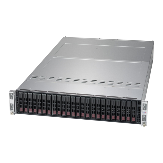
Page 10: Chassis Features
SuperServer 2028BT-Hxxx Chassis Features The SC217BHQ+-R2K22BP chassis houses four separate computing nodes, each containing its own motherboard. System Power The system features dual redundant 2200 W power supplies consisting of two hot-plug power modules. They have 80 Plus certification at Titanium Level (96%) high-efficiency. -
Page 11: Contacting Supermicro
Super Micro Computer, Inc. 980 Rock Ave. San Jose, CA 95131 U.S.A. Tel: +1 (408) 503-8000 Fax: +1 (408) 503-8008 Email: marketing@supermicro.com (General Information) support@supermicro.com (Technical Support) Web Site: www.supermicro.com Europe Address: Super Micro Computer B.V. Het Sterrenbeeld 28, 5215 ML... - Page 12 SuperServer 2028BT-Hxxx Notes...
-
Page 13: Chapter 2 Rack Installation
Chapter 2 Rack Installation This chapter provides instructions for preparing and mounting your chassis in a rack. Unpacking the System You should inspect the box the chassis was shipped in and note if it was damaged in any way. If the chassis itself shows damage, file a damage claim with the carrier who delivered it. -
Page 14: Warnings And Precautions
SuperServer 2028BT-Hxxx User Manual Warnings and Precautions Rack Precautions • Ensure that the leveling jacks on the bottom of the rack are fully extended to the floor with the full weight of the rack resting on them. • In single rack installations, stabilizers should be attached to the rack. •... -
Page 15: Rack Mounting Considerations
Rack Mounting Considerations Ambient Operating Temperature If installed in a closed or multi-unit rack assembly, the ambient operating temperature of the rack environment may be greater than the ambient temperature of the room. Therefore, consideration should be given to installing the equipment in an environment compatible with the manufacturer’s maximum rated ambient temperature (TMRA). -
Page 16: Rack Mounting Instructions
SuperServer 2028BT-Hxxx User Manual Rack Mounting Instructions This section provides information on installing the chassis into a rack unit with the rails provided. There are a variety of rack units on the market, which may mean that the assembly procedure will differ slightly from the instructions provided. You should also refer to the installation instructions that came with the rack unit you are using. -
Page 17: Installing The Rails On A Rack
Installing the Rails on a Rack 1. Loosen the adjusting screw to allow the rear section to slide in the front section. 2. Push the small hooks on the front section of the rail into the holes on the front post of the rack and then down, until the spring-loaded pegs snap into the rack holes. -
Page 18: Chassis Installation
SuperServer 2028BT-Hxxx User Manual Chassis Installation Slide the chassis into the rack so that the bottom of the chassis slides onto the bottom lip of the rail. Figure 2-3. Sliding the Chassis into the Rack Stability hazard. The rack stabilizing mechanism must be in place, or the rack must be bolted to the floor before you slide the unit out for servicing. -
Page 19: Chapter 3 System Interface
Chapter 3: System Interface Chapter 3 System Interface Overview The ares four control panel on the front outside edges of the chassis. Each contorl panel houses power buttons and status monitoring lights for one node. The externally accessible hard drives display status lights. The power supply displays status lights visible from the back of the chassis. -
Page 20: Control Panel Buttons
SuperServer 2028BT-Hxxx User Manual Control Panel Buttons The chassis control panel includes two push-buttons that controls power. Power The main power switch applies or removes primary power from the power supply to the computing nodes but maintains standby power. To perform most maintenance tasks, unplug the system to remove all power. -
Page 21: Information Led
Chapter 3: System Interface Information LED Alerts operator to several states, as noted in the table below Information LED Status Description An overheat condition has occurred. Continuously on and red (This may be caused by cable congestion.) Blinking red (1Hz) Fan failure, check for an inoperative fan. -
Page 22: Drive Carrier Leds
SuperServer 2028BT-Hxxx User Manual Drive Carrier LEDs The chassis includes externally accessible SAS/SATA/NVMe drives. Each drive carrier displays two LED indicators: an activity indicator and a status indicator. The status indicator functions in RAID configurations. For non-RAID configurations, it remains off. See the table below for details. LED Color Blinking Pattern Behavior for Device... -
Page 23: Chapter 4 Advanced Motherboard Setup
Chapter 4: Advanced Motherboard Setup Chapter 4 Advanced Motherboard Setup This chapter covers the steps required to install processors and heatsinks to the X10DRT-B+ motherboard, connect the data and power cables and install add-on cards. All motherboard jumpers and connections are described and a layout and quick reference chart are included in this chapter. -
Page 24: Installing The Processor And Heatsink
• Install the processor into the CPU socket before installing the heatsink. • Refer to the Supermicro web site for updates on CPU support. Installing an LGA 2011 Processor Installing a CPU 1. There are two levers on the LGA 2011 socket. - Page 25 Chapter 4: Advanced Motherboard Setup 3. W ith the sec ond lever f ully Open the load plate. retracted, gently push down on the "Open 1st" lever to loosen the load plate. Lift the load plate with your fingers to open it completely. 4.
- Page 26 uperServer 2028BT-Hxxx User's Manual Gently close the load plate. 7. With the "Close 1st" lever fully retracted, gently close the load plate. Push down and lock the lever labeled "Close 1st". 8. Make sure the locking mechanism on the "Close 1st" lever catches the lip of the load plate.
-
Page 27: Installing A Cpu Heatsink
Chapter 4: Advanced Motherboard Setup Installing a CPU Heatsink Installing a Heatsink 1. Place the heatsink on top of the CPU so that the four mounting holes are aligned with those on the retention mechanism. The heatsink fins should be parallel with the chassis ariflow from the fans.. -
Page 28: Removing The Heatsink
uperServer 2028BT-Hxxx User's Manual Removing the Heatsink Caution: We do not recommend removing the CPU or the heatsink. If you do need to remove the heatsink, please follow the instructions below to prevent damage to the CPU or the CPU socket. 1. -
Page 29: I/O Ports
LAN port is supported by the ASpeed AST2400 Baseboard Management Controller (BMC), and accepts an RJ45 type cable. For more information on IPMI, refer to the IPMI User's Guide on the Supermicro website. Unit Identifier Buttons/LED Indicators The front and back of the server have a blue unit identifier (UID) LED to help an operator find the server in a rack. -
Page 30: Installing Memory
For best performance, install memory modules of the same type and same speed in the slots as indicated in the tables on the following page. Note: Check the Supermicro web site for recommended memory modules. CAUTION Exercise extreme care when installing or removing DIMM modules to prevent any possible damage. -
Page 31: Memory Support
The server features 24 DIMM slots that can support up to 3 TB of Load Reduced (LRDIMM 3DS), 1.5 TB LRDIMM, or 768 registered (RDIMM) ECC DDR4- 2400/2133/1866/1600/1333 SDRAM or LRDIMM type memory. For the latest memory updates, refer to the Supermicro website at www.supermicro.com/products/ motherboard. -
Page 32: Memory Support For E4-2600 (V3/V4)-Based Motherboards
uperServer 2028BT-Hxxx User's Manual Memory Support for E4-2600 (v3/v4)-based Motherboards Populating RDIMM/LRDIMM DDR4 Memory Modules Speed (MT/s); Voltage (V); Slots per Channel (SPC) and DIMMs per Channel (DPC) Ranks 3 Slots per Channel DIMM Capacity DIMM (GB) 1 DPC 2 DPC 3 DPC Type Data... -
Page 33: Motherboard Details
Chapter 4: Advanced Motherboard Setup Motherboard Details UID_LED1 USB0/1 IPMI_LAN (3.0) JBAT1 BMC_HB_LED1 Battery FAN3 BIOS FAN4 SIOM: CPU1 PCI-E 3.0 X16 FLASH IPMI CODE C612 BIOS JBT1 LICENSE X10DRT-B+ Rev. 1.01 JSD1 CPU1 OPEN 1st CPU2 BAR CODE Figure 4-4. SUPER X10DRT-B+ Layout Notes: "... -
Page 34: Motherboard Quick Reference
uperServer 2028BT-Hxxx User's Manual Motherboard Quick Reference Jumper Description Default Setting JBT1 Clear CMOS See Section 4-7 JPB1 Baseboard Management Pins 1-2 (Enabled) Controller (BMC) Enable JPG1 VGA Enable Pins 1-2 (Enabled) JPME2 Manufacturing Mode Pins 1-2 (Normal) JWD1 Watch Dog Timer Enable Pins 1-2 (Reset) JVRM1/2 C Bus for VRM... -
Page 35: Connector Definitions
Chapter 4: Advanced Motherboard Setup Connector Definitions Power & Front Control Panel Connector (JF1) Main power to the motherboard is supplied through an adapter card on each node that connects to the system midplane which receives power directly from the power supply. -
Page 36: Other Connectors
uperServer 2028BT-Hxxx User's Manual Other Connectors Fan Headers Fan Header Pin Definitions The motherboard has two fan Pin# Definition headers (FAN3, FAN4). All are 4-pin Ground fans headers, which are backward +12V compatible with traditional 3-pin fans. Tachometer Fan speed control is available for Pulse Width 4-pin fans only. -
Page 37: Jumper Settings
Chapter 4: Advanced Motherboard Setup Jumper Settings Explanation of Jumpers To modify the operation of the motherboard, jumpers can be used Connector to choose between optional settings. Pins Jumpers create shorts between two pins to change the function of the Jumper connector. - Page 38 uperServer 2028BT-Hxxx User's Manual VGA Enable/Disable JPG1 allows you to enable or disable VGA Enable/Disable Jumper Settings the onboard VGA port. The default Jumper Setting Definition position is on pins 1 and 2 to enable Pins 1-2 Enabled VGA. Pins 2-3 Disabled Watch Dog Enable/Disable JWD1 controls the Watch Dog...
- Page 39 Chapter 4: Advanced Motherboard Setup ME Manufacturing Mode Select Close pin 2 and pin 3 of jumper JPME2 to bypass SPI flash security ME Mode Select Jumper Settings and force the system to operate in Jumper Setting Definition the Manufacturer (ME) mode, allowing the user to flash the system firmware Pins 1-2 Normal...
-
Page 40: Onboard Indicators
uperServer 2028BT-Hxxx User's Manual LAN 1/LAN 2 Onboard Indicators Link LED Activity LED IPMI Dedicated LAN LEDs A dedicated IPMI LAN port is located IPMI LAN on the rear I/O panel. The amber LED IPMI LAN Link LED (Left) & (X8ST3-F) on the right indicates activity, while the Activity LED (Right) -
Page 41: Pcie Slots And Sata
A SATA DOM (Device - on- Disk) is Pin# Signal located at S-SATA3 on the motherboard. Ground S-SATA3 is used with a Supermicro SATA_TXP SuperDOM, which is a yellow SATA SATA_TXN DOM connector with a power pin built in, Ground and no external power supply is needed. -
Page 42: 4-10 Installing Software
2028BT-Hxxx User's Manual 4-10 Installing Software The Supermicro FTP site contains drivers and utilities for your system at ftp://ftp. supermicro.com. Some of these must be installed, such as the chipset driver. After accessing the FTP site, go into the CDR_Images directory and locate the ISO file for your motherboard. -
Page 43: Superdoctor ® 5
Chapter 4: Advanced Motherboard Setup SuperDoctor ® The Supermicro SuperDoctor 5 is a hardware and operating system services monitoring program that functions in a command-line or web-based interface in Windows and Linux operating systems. The program monitors system health information such as CPU temperature, system voltages, system power consumption, fan speed, and provides alerts via email or Simple Network Management Protocol (SNMP). -
Page 44: 4-11 Onboard Battery
Figure 4-8. SuperDoctor 5 Interface Display Screen (Remote Control) Note: The SuperDoctor 5 program and User’s Manual can be downloaded from the Supermicro web site at http://www.supermicro.com/products/nfo/sms_sd5.cfm. For Linux, we recommend that you use the SuperDoctor II application instead. 4-11 Onboard Battery Please handle used batteries carefully. -
Page 45: Chapter 5 Chassis Setup And Maintenance
Chapter 5: Chassis Setup and Maintenance Chapter 5 Chassis Setup and Maintenance Overview This chapter covers the steps required to install components and perform maintenance on the chassis. The only tool required is a Phillips screwdriver. Review the warnings and precautions listed in the manual before setting up or servicing this chassis. -
Page 46: Removing Power From The System
SuperServer 2028BT-Hxxx User Manual Figure 5-3. Node Tray (1 of 4) Removing Power from the System Before performing some setup or maintenance tasks, use the following procedure to ensure that power has been removed from the system. Removing Power from a Node 1. -
Page 47: Accessing The System
Chapter 5: Chassis Setup and Maintenance Accessing the System Removing a Computing Node Drawer Node Release Handle Node Handle Figure 5-4. Removing a Node Tray Removing a Node 1. Use the operating system to power down the node. 2. Pull down the node release handle and use both handles to slide the node out the chassis rear. -
Page 48: Removing The Chassis Cover
SuperServer 2028BT-Hxxx User Manual Removing the Chassis Cover You can access some chassis components, such as fans, by removing the cover. Remove two screws Figure 5-5. Removing the Chassis Cover Removing the Chassis Cover 1. Power down the power supplies as described in Section 5-2. 2. -
Page 49: Storage Drives
Each node controls a set of six hard drives. If a node drawer is pulled out of the chassis, the hard drives associated with that node will power down. Note: Enterprise level hard disk drives are recommended for use in Supermicro servers. For information on recommended drives, visit the Supermicro website. - Page 50 SuperServer 2028BT-Hxxx User Manual Removing Hard Drive Carriers from the Chassis 1. Press the release button on the drive carrier. This extends the drive bay handle. 2. Use the handle to pull the drive out of the chassis (Figure 5-6). 3.
- Page 51 Chapter 5: Chassis Setup and Maintenance Figure 5-8. Removing Dummy Drive from Carrier Installing a Drive into the Carrier 1. Install a new drive into the carrier with the printed circuit board side facing down so that the mounting holes in the drive align with those in the carrier. 2.
-
Page 52: Installing The Expansion Cards
SuperServer 2028BT-Hxxx User Manual Installing the Expansion Cards The system can accommodate two low-profile cards per node, for a total of eight in the chassis. Installing an Expansion Card 1. Power down the node and remove it from the chassis. 2. -
Page 53: Siom Card
Chapter 5: Chassis Setup and Maintenance SIOM Card The Supermicro Input/Output module (SIOM) card provides options for network connection. It is inserted into a SIOM slot on the motherboard. This installation is usually performed by a system integrator or manufacturer. -
Page 54: System Fans
SuperServer 2028BT-Hxxx User Manual System Fans Four fans provide cooling for the system. Figure 5-12. System Fan Placement Changing a System Fan 1. If necessary, open the chassis while the system is running to determine which fan has failed. Never run the server for an extended period of time with the chassis cover open. - Page 55 Chapter 5: Chassis Setup and Maintenance Figure 5-13. Replacing a System Fan in the Fan Housing 7. Place the replacement fan into the vacant space in the housing while making sure the arrows on the top of the fan (indicating air direction) point in the same direction as the arrows on the other fans.
-
Page 56: Air Shrouds
SuperServer 2028BT-Hxxx User Manual Air Shrouds Installing the Air Shroud Air shrouds concentrate airflow to maximize fan efficiency. An air shroud is required for each motherboard node. Installing an Air Shroud 1. Make sure that the motherboard expansion card (if applicable) and all components are properly installed in each motherboard node. -
Page 57: Power Supply
The chassis features redundant power supplies. The power modules can be changed without powering down the system. New units can be ordered directly from Supermicro or authorized distributors. These power supplies are auto-switching capable. This feature enables them to automatically sense the input voltage and operate at a 100-120v or 180-240v. - Page 58 SuperServer 2028BT-Hxxx User Manual Notes 5-14...
-
Page 59: Chapter 6 Bios
Chapter 6: BIOS Chapter 6 BIOS Introduction This chapter describes the AMI BIOS setup utility for the X10DRT-B+ motherboard. It also provides the instructions on how to navigate the AMI BIOS setup utility screens. The AMI ROM BIOS is stored in a Flash EEPROM and can be easily updated. Note: Due to periodic changes to the BIOS, some settings may have been added or deleted since this manual was published. -
Page 60: Main Setup
MM/DD/YYYY format. The time is entered in HH:MM:SS format. Note: The time is in the 24-hour format. For example, 5:30 P.M. appears as 17:30:00. The date's default value is 01/01/2016 after RTC reset. Supermicro X10DRT-B+ (Motherboard model) BIOS Version Build Date (of the BIOS) CPLD Version: This item displays when the version of the CPLD (Complex Programmable Logic Device) used in the system was built. -
Page 61: Advanced Setup Configurations
Chapter 6: BIOS Advanced Setup Configurations Use the arrow keys to select Advanced Setup and press <Enter> to access the following submenu items. Warning: Take Caution when changing the Advanced settings. An incorrect value, an incorrect DRAM frequency, or an incorrect timing setting may cause the system to malfunction. -
Page 62: Power Configuration
SuperServer 2028BT-Hxxx User’s Manual Wait For 'F1' If Error Select Enabled to force the system to wait until the 'F1' key is pressed if an error occurs. The options are Disabled and Enabled. INT19 (Interrupt 19) Trap Response Interrupt 19 is the software interrupt that handles the boot disk function. When this item is set to Immediate, the ROM BIOS of the host adaptors will "capture"... -
Page 63: Cpu Configuration
Chapter 6: BIOS CPU Configuration This submenu displays the following information regarding the CPU installed in Socket 1 and (or) Socket 2 as detected by the BIOS. • Processor Socket • Processor ID • Processor Frequency • Processor Maximum Ratio •... - Page 64 SuperServer 2028BT-Hxxx User’s Manual can execute and where it cannot, thus preventing a worm or a virus from flooding illegal codes to overwhelm the processor or damage the system during an attack. The options are Enable and Disable. (Refer to Intel and Microsoft Web sites for more information.) PPIN Control Select Unlock/Enable to use the Protected-Processor Inventory Number (PPIN) in...
-
Page 65: Advanced Power Management Configuration
Chapter 6: BIOS Intel Virtualization Technology (Available when supported by the CPU) Select Enable to support Intel Virtualization Technology, which will allow one platform to run multiple operating systems and applications in independent partitions, creating multiple "virtual" systems in one physical computer. The options are Enable and Disable. - Page 66 SuperServer 2028BT-Hxxx User’s Manual CPU P State Control (Available when Power Technology is set to Custom) EIST (P-States) EIST (Enhanced Intel SpeedStep Technology) allows the system to automatically adjust processor voltage and core frequency to reduce power consumption and heat dissipation.
-
Page 67: Chipset Configuration
Chapter 6: BIOS CPU C3 Report Select Enable to allow the BIOS to report the CPU C3 State (ACPI C2) to the operating system. During the CPU C3 State, the CPU clock generator is turned off. The options are Enable and Disable. CPU C6 Report Select Enable to allow the BIOS to report the CPU C6 State (ACPI C3) to the operating system. - Page 68 SuperServer 2028BT-Hxxx User’s Manual Snoop Response Hold Off User this feature to set the value of the Snoop Response Hold-Off setting. The default setting is 256 cycle. IIO1 Configuration IOU2 (II01 PCIE Port 1) Use this item to configure the PCI-E port Bifuraction setting for a PCI-E port specified by the user.
-
Page 69: Ioat Configuration
Chapter 6: BIOS IOU2 Non-Posted Prefetch Select Enable to use the function of Non-Posted Prefetch on the slot specified by the user. The options are Enable and Disable. IOAT Configuration Enable IOAT (I/O Acceleration Technology) Select Enable to enable Intel I/OAT (I/O Acceleration Technology), which significantly reduces CPU overhead by leveraging CPU architectural improvements and freeing the system resource for other tasks. - Page 70 SuperServer 2028BT-Hxxx User’s Manual QPI (Quick Path Interconnect) Configuration The following QPI information will be displayed: • Number of CPU • Number of II0 • Current QPI Link Speed: This item displays the current QPI Link speed. • Current QPI Link Frequency: This item displays the frequency of the QPI Link.
-
Page 71: Memory Configuration
Chapter 6: BIOS Isoc Mode Select Enable to enable Isochronous support to meet QoS (Quality of Service) requirements. This feature is especially important for Virtualization Technology. The options are Enable and Disable. Memory Configuration Integrated Memory Controller (IMC) Enforce POR Select Enable to enforce POR restrictions on DDR4 frequency and voltage programming. -
Page 72: Dimm Information
SuperServer 2028BT-Hxxx User’s Manual DIMM Information This item displays the status of a DIMM module specified by the user. • P1-DIMMA1/A2/A3 • P1-DIMMB1/B2/B3 • P1-DIMMC1/C2/C3 • P1-DIMMD1/D2/D3 • P2-DIMME1/E2/E3 • P2-DIMMF1/F2/F3 • P2-DIMMG1/G2/G3 • P2-DIMMH1/H2/H3 Memory RAS (Reliability_Availability_Serviceability) Configuration Use this submenu to configure the following Memory RAS settings. Memory RAS Configuration Setup RAS Mode Use this feature to configure memory RAS settings. -
Page 73: South Bridge Configuration
Chapter 6: BIOS Patrol Scrub Interval This feature allows you to decide how many hours the system should wait before the next complete patrol scrub is performed. Use the keyboard to enter a value from 0-24. The default setting is 24. Demand Scrub Demand Scrubbing is a process that allows the CPU to correct correctable memory errors found on a memory module. -
Page 74: Sata Configuration
SuperServer 2028BT-Hxxx User’s Manual Port 60/64 Emulation Select Enabled for I/O port 60h/64h emulation support, which in turn, will provide complete legacy USB keyboard support for the operating systems that do not support legacy USB devices. The options are Disabled and Enabled. USB 3.0 Support Select Enabled for USB 3.0 support. - Page 75 Chapter 6: BIOS SATA Support Aggressive Link Power Management When this item is set to Enabled, the SATA AHCI controller manages the power usage of the SATA link. The controller will put the link to a low power state when the I/O is inactive for an extended period of time, and the power state will return to normal when the I/O becomes active.
- Page 76 SuperServer 2028BT-Hxxx User’s Manual *If the item above "Configure SATA as" is set to RAID, the following items will display: SATA Support Aggressive Link Power Management When this item is set to Enabled, the SATA AHCI controller manages the power usage of the SATA link.
- Page 77 Chapter 6: BIOS sSATA Configuration When this submenu is selected, AMI BIOS automatically detects the presence of the SATA devices that are supported by the PCH controller and displays the following items: sSATA Controller This item enables or disables the onboard SATA controller supported by the Intel PCH-sSATA controller.
- Page 78 SuperServer 2028BT-Hxxx User’s Manual Port 0 ~ Port 3 sSATA Device Type Use this item to specify if the sSATA port specified by the user should be connected to a Solid State drive or a Hard Disk Drive. The options are Hard Disk Drive and Solid State Drive.
- Page 79 Chapter 6: BIOS sSATA Port 0~ Port 3 Select Enabled to enable an sSATA port specified by the user. The options are Disabled and Enabled. sSATA Port 0 ~ Port 3 Hot Plug Set this item to Enabled for hot-plugging support, which will allow the user to replace an sSATA drive without shutting down the system.
- Page 80 SuperServer 2028BT-Hxxx User’s Manual PCI Devices Common Settings: PCI Latency Timer Use this item to configure the PCI latency timer for a device installed on a PCI bus. Select 32 to set the PCI latency timer to 32 PCI clock cycles. The options are 32, 64, 96, 128, 160, 192, 224 and 248 (PCI Bus Clocks).
- Page 81 Chapter 6: BIOS MMIO High Size Use this item to select the high memory size according to memory-address mapping for the IO hub. The options are 256 GB, 128 GB, 512 GB, and 1024 GB. RSC-R1UTP-E16R PCI-E 3.0 x16 OPROM/CPU1 PCI-E 3.0 x4 OPROM/ RSC-P-6 PCI-E 3.0 x16 OPROM 1/CPU2 SXB2A PCI-E 3.0 x8 OPROM/CPU2 SXB2B PCI-E 3.0 x16 OPROM Use this feature to select the type of device to be installed on the PCI-E slot...
-
Page 82: Super Io Configuration
SuperServer 2028BT-Hxxx User’s Manual Ipv6PXE Support (Available when Network Stack is set to Enabled) Select Enabled to enable Ipv6 PXE (Preboot Execution Environment) for boot support. If this feature is set to Disabled, Ipv6 PXE boot option will not be supported. - Page 83 Chapter 6: BIOS *If the item above set to Enabled, the following items will become available for configuration: COM1 Console Redirection Settings Terminal Type This feature allows the user to select the target terminal emulation type for Console Redirection. Select VT100 to use the ASCII Character set. Select VT100+ to add color and function key support.
- Page 84 SuperServer 2028BT-Hxxx User’s Manual when the receiving buffer is full. Send a "Start" signal to start sending data when the receiving buffer is empty. The options are None and Hardware RTS/CTS. VT-UTF8 Combo Key Support Select Enabled to enable VT-UTF8 Combination Key support for ANSI/VT100 terminals.
- Page 85 Chapter 6: BIOS COM2/SOL Console Redirection Settings Use this feature to specify how the host computer will exchange data with the client computer, which is the remote computer used by the user. Terminal Type Use this feature to select the target terminal emulation type for Console Redirection.
- Page 86 SuperServer 2028BT-Hxxx User’s Manual VT-UTF8 Combo Key Support Select Enabled to enable VT-UTF8 Combination Key support for ANSI/VT100 terminals. The options are Enabled and Disabled. Recorder Mode Select Enabled to capture the data displayed on a terminal and send it as text messages to a remote server.
-
Page 87: Acpi Settings
Chapter 6: BIOS color and function key support. Select ANSI to use the extended ASCII character set. Select VT-UTF8 to use UTF8 encoding to map Unicode characters into one or more bytes. The options are ANSI, VT100, VT100+, and VT-UTF8. Bits Per Second This item sets the transmission speed for a serial port used in Console Redirection. -
Page 88: Iscsi Configuration
SuperServer 2028BT-Hxxx User’s Manual iSCSi Configuration iSCSI Initiator Name This feature allows the user to enter the unique name of the iSCSI Initiator in IQN format. Once the name of the iSCSI Initiator is entered into the system, configure the proper settings for the following items. -
Page 89: Event Logs
Chapter 6: BIOS Event Logs Use this tab page to configure Event Log settings. Change SMBIOS Event Log Settings This feature allows the user to configure SMBIOS Event settings. Enabling/Disabling Options SMBIOS Event Log Select Enabled to enable SMBIOS (System Management BIOS) Event Logging during system boot. -
Page 90: View Smbios Event Log
SuperServer 2028BT-Hxxx User’s Manual When Log is Full Select Erase Immediately to immediately erase all errors in the SMBIOS event log when the event log is full. Select Do Nothing for the system to do nothing when the SMBIOS event log is full. The options are Do Nothing and Erase Immediately. SMBIOS Event Log Standard Settings Log System Boot Event Select Enabled to log system boot events. -
Page 91: Ipmi Settings
Chapter 6: BIOS IPMI Settings Use this tab page to configure Intelligent Platform Management Interface (IPMI) settings. BMC (Baseboard Management Controller) Firmware Revision This item indicates the IPMI firmware revision used in your system. IPMI Status This item indicates the status of the IPMI firmware installed in your system. System Event Log ... -
Page 92: Bmc Network Configuration
SuperServer 2028BT-Hxxx User’s Manual When SEL is Full This feature allows the user to determine what the BIOS should do when the system event log is full. Select Erase Immediately to erase all events in the log when the system event log is full. Please note that you will need to reboot the system for the changes to take effect. -
Page 93: Security Settings
Chapter 6: BIOS VLAN Select Enable for VLAN port support. Security Settings Use this tab page to configure Security settings. Password Check If this feature is set to Setup, a password is required for a user to enter the BIOS Setup utility. -
Page 94: Secure Boot Menu
SuperServer 2028BT-Hxxx User’s Manual Secure Boot Menu The following items will display: • System Mode • Secure Boot • Vendor Keys Secure Boot Select Enable for secure boot support to ensure system security at bootup. The options are Enabled and Disabled. Secure Boot Mode This item allows the user to select the desired secure boot mode for the system. - Page 95 Chapter 6: BIOS Key Exchange Key This feature allows the user to configure and save Key-Exchange-Key settings. Authorized Signatures This feature allows the user to set and save authorized signatures and grant access to those whose names appear on the list. Forbidden Signatures ...
-
Page 96: Boot Settings
SuperServer 2028BT-Hxxx User’s Manual Boot Settings Use this tab page to configure Intelligent Platform Management Interface (IPMI) settings. Boot Configuration Setup Prompt Timeout This feature allows the user to determine how long the system should wait for the setup activation key before it boots up. The default setting is 1 (second). Boot Mode Select Use this item to select the type of device to be used for system boot. -
Page 97: Delete Boot Option
Chapter 6: BIOS Legacy Boot Option #1 - Legacy Boot Option #7 When the item above -"Boot Mode Select" is set to UEFI, the following items will be display for configuration: UEFI Boot Option #1 - UEFI Boot Option #8 ... -
Page 98: Save & Exit
SuperServer 2028BT-Hxxx User’s Manual Save & Exit Use this tab page to configure Save & Exit settings. Discard Changes and Exit Select this option to quit the BIOS setup without making permanent changes to the system configuration, and reboot the computer. Select Discard Changes and Exit from the Exit menu and press <Enter>. - Page 99 Chapter 6: BIOS Restore Optimized Defaults To set this feature, select Restore Optimized Defaults from the Exit menu and press <Enter>. These are manufacturer default settings designed for maximum system performance but not for maximum stability. Save As User Defaults To set this feature, select Save as User Defaults from the Exit menu and press <Enter>.
- Page 100 SuperServer 2028BT-Hxxx User’s Manual Notes 6-42...
-
Page 101: Appendix A Bios Error Beep Codes
Appendix A: BIOS Error Beep Codes Appendix A BIOS Error Beep Codes During the POST (Power-On Self-Test) routines, which are performed at each system boot, errors may occur. Non-fatal errors are those which, in most cases, allow the system to continue to boot. - Page 102 SuperServer 2028BT-Hxxx Notes...
-
Page 103: Appendix B Standardized Warning Statements For Ac Systems
Only certified technicians should attempt to install or configure components. Read this chapter in its entirety before installing or configuring components in the Supermicro chassis. Some warnings may not apply for your system. These warnings may also be found on our web site at www.supermicro.com/about/ policies/safety_information.cfm. - Page 104 SuperServer 2028BT-Hxxx User Manual Warnung WICHTIGE SICHERHEITSHINWEISE Dieses Warnsymbol bedeutet Gefahr. Sie befinden sich in einer Situation, die zu Verletzungen führen kann. Machen Sie sich vor der Arbeit mit Geräten mit den Gefahren elektrischer Schaltungen und den üblichen Verfahren zur Vorbeugung vor Unfällen vertraut.
- Page 105 Appendix B: Warning Statements for AC Systems جسذٌة اصابة ًتتسبب ف حالة ٌوكي أى ًاًك ف خطز ًٌٌع هذا الزهز !تحذٌز الذوائز بالوخاطز الٌاجوة عي ي على علن ، ك هعذات تعول على أي قبل أى الكهزبائٍة حىادث أي وقىع وٌع...
-
Page 106: Installation Instructions
SuperServer 2028BT-Hxxx User Manual Installation Instructions Warning! Read the installation instructions before connecting the system to the power source. 設置手順書 システムを電源に接続する前に、 設置手順書をお読み下さい。 警告 将此系统连接电源前,请先阅读安装说明。 警告 將系統與電源連接前,請先閱讀安裝說明。 Warnung Vor dem Anschließen des Systems an die Stromquelle die Installationsanweisungen lesen. ¡Advertencia! Lea las instrucciones de instalación antes de conectar el sistema a la red de alimentación. -
Page 107: Circuit Breaker
Appendix B: Warning Statements for AC Systems Circuit Breaker Warning! This product relies on the building's installation for short-circuit (overcurrent) protection. Ensure that the protective device is rated not greater than: 250 V, 20 A. サーキッ ト ・ ブレーカー この製品は、 短絡 (過電流) 保護装置がある建物での設置を前提としています。 保護装置の定格が250 V、... -
Page 108: Power Disconnection Warning
SuperServer 2028BT-Hxxx User Manual 경고! 이 제품은 전원의 단락(과전류)방지에 대해서 전적으로 건물의 관련 설비에 의존합니다. 보호장치의 정격이 반드시 250V(볼트), 20A(암페어)를 초과하지 않도록 해야 합니다. Waarschuwing Dit product is afhankelijk van de kortsluitbeveiliging (overspanning) van uw electrische installatie. Controleer of het beveiligde aparaat niet groter gedimensioneerd is dan 220V, 20A. - Page 109 Appendix B: Warning Statements for AC Systems ¡Advertencia! El sistema debe ser disconnected de todas las fuentes de energía y del cable eléctrico quitado de los módulos de fuente de alimentación antes de tener acceso el interior del chasis para instalar o para quitar componentes de sistema. Attention Le système doit être débranché...
-
Page 110: Equipment Installation
SuperServer 2028BT-Hxxx User Manual Equipment Installation Warning! Only trained and qualified personnel should be allowed to install, replace, or service this equipment. 機器の設置 トレーニングを受け認定された人だけがこの装置の設置、 交換、 またはサービスを許可 されています。 警告 只有经过培训且具有资格的人员才能进行此设备的安装、更换和维修。 警告 只有經過受訓且具資格人員才可安裝、更換與維修此設備。 Warnung Das Installieren, Ersetzen oder Bedienen dieser Ausrüstung sollte nur geschultem, qualifiziertem Personal gestattet werden. -
Page 111: Restricted Area
Appendix B: Warning Statements for AC Systems Waarschuwing Deze apparatuur mag alleen worden geïnstalleerd, vervangen of hersteld door geschoold en gekwalificeerd personeel. Restricted Area Warning! This unit is intended for installation in restricted access areas. A restricted access area can be accessed only through the use of a special tool, lock and key, or other means of security. -
Page 112: Battery Handling
SuperServer 2028BT-Hxxx User Manual אזור עם גישה מוגבלת !אזהרה יש להתקין את היחידה באזורים שיש בהם הגבלת גישה. הגישה ניתנת בעזרת .)'כלי אבטחה בלבד (מפתח, מנעול וכד محظورة مناطق ٍنتركُبها ف هذه انىحذة تخصيص تم ،أداة خاصت من خالل استخذاو فقط... - Page 113 Appendix B: Warning Statements for AC Systems Warnung Bei Einsetzen einer falschen Batterie besteht Explosionsgefahr. Ersetzen Sie die Batterie nur durch den gleichen oder vom Hersteller empfohlenen Batterietyp. Entsorgen Sie die benutzten Batterien nach den Anweisungen des Herstellers. Attention Danger d'explosion si la pile n'est pas remplacée correctement. Ne la remplacer que par une pile de type semblable ou équivalent, recommandée par le fabricant.
- Page 114 SuperServer 2028BT-Hxxx User Manual Redundant Power Supplies (if applicable to your system) Warning! This unit might have more than one power supply connection. All connections must be removed to de-energize the unit. 冗長電源装置 このユニッ トは複数の電源装置が接続されている場合があります。 ユニッ トの電源を切るためには、 すべての接続を取り外さなければなりません。 警告 此部件连接的电源可能不止一个,必须将所有电源断开才能停止给该部件供电。 警告...
- Page 115 Appendix B: Warning Statements for AC Systems امداد الطاقة بوحدات عدة اتصاالت جهاز ال يكون لهذا قد الكهرباء عن وحدة ال لعسل كافة االتصاالت يجب إزالة 경고! 이 장치에는 한 개 이상의 전원 공급 단자가 연결되어 있을 수 있습니다. 이 장치에...
-
Page 116: Comply With Local And National Electrical Codes
SuperServer 2028BT-Hxxx User Manual מתח בפנל האחורי !הרה אז קיימת סכנת מתח בפנל האחורי בזמן תפעול המערכת. יש להיזהר במהלך .העבודה اللىحة أوالطاقة المىجىدة على التيار الكهزبائي مه خطز هناك هذا الجهاس خدمة كه حذرا عند يعمل النظام عندما يكىن 경고! 시스템이... -
Page 117: Product Disposal
Appendix B: Warning Statements for AC Systems Attention L'équipement doit être installé conformément aux normes électriques nationales et locales. תיאום חוקי החשמל הארצי !אזהרה הציוד חייבת להיות תואמת לחוקי החשמל המקומיים והארציים התקנת المتعلقة المحلية والىطىية قىاويه يجب أن يمتثل لل الكهربائية... -
Page 118: Hot Swap Fan Warning
SuperServer 2028BT-Hxxx User Manual ¡Advertencia! Al deshacerse por completo de este producto debe seguir todas las leyes y reglamentos nacionales. Attention La mise au rebut ou le recyclage de ce produit sont généralement soumis à des lois et/ou directives de respect de l'environnement. Renseignez-vous auprès de l'organisme compétent. - Page 119 Appendix B: Warning Statements for AC Systems 警告 危險的可移動性零件。請務必與轉動的風扇葉片保持距離。 當您從機架移除風扇裝 置,風扇可能仍在轉動。小心不要將手指、螺絲起子和其他物品太靠近風扇。 Warnung Gefährlich Bewegende Teile. Von den bewegenden Lüfterblätter fern halten. Die Lüfter drehen sich u. U. noch, wenn die Lüfterbaugruppe aus dem Chassis genommen wird. Halten Sie Finger, Schraubendreher und andere Gegenstände von den Öffnungen des Lüftergehäuses entfernt.
- Page 120 Verbindungskabeln, Stromkabeln und/oder Adapater, die Ihre örtlichen Sicherheitsstandards einhalten. Der Gebrauch von anderen Kabeln und Adapter können Fehlfunktionen oder Feuer verursachen. Die Richtlinien untersagen das Nutzen von UL oder CAS zertifizierten Kabeln (mit UL/CSA gekennzeichnet), an Geräten oder Produkten die nicht mit Supermicro gekennzeichnet sind. B-18...
- Page 121 םילבכב שמתשהל רוסיא םייק ,תוחיטבה יקוחו למשחה ירישכמב שומישה יקוחל םאתהב -ב םיכמסומהUL -ב ואCSA (( לש דוק םהילע עיפומ רשאכUL/CSA ילמשח רצומ לכ רובע י"ע םאתוה רשא רצומב קר אלא ,רחאSupermicro .דבלב تالباكلا ءارشب مق وأ ةددحملا وأ ةرفوتملا تاليصوتلا مادختساب مق ،جتنملا بيكرت دنع...
- Page 122 Het gebruik van niet geschikte Kabels en/of Adapters kan een storing of brand veroorzaken. Wetgeving voor Elektrische apparatuur en Materiaalveiligheid verbied het gebruik van UL of CSA -gecertificeerde Kabels (met UL/CSA in de code) voor elke andere toepassing dan de door Supermicro hiervoor beoogde Producten. B-20...
-
Page 123: Appendix C System Specifications
Appendix C: System Specifications Appendix C System Specifications Processors Single or dual Intel E5-2600 v3/v4 Series processors in LGA2011 sockets Note: Please refer to our web site for a complete listing of supported processors. Chipset Intel PCH C612 chipset BIOS 16 MB AMI SPI Flash EEPROM Memory Capacity Twenty-four DIMM slots support 3 TB of Load Reduced (LRDIMM 3DS), 1.5 TB... -
Page 124: System Cooling
SuperServer 2028BT-Hxxx System Cooling Four 8cm PWM cooling fans; two air shrouds; two CPU heat sinks System Input Requirements AC Input Voltage: 100-127 V, 50-60 Hz, or 200-240 V, 50-60 Hz Power Supply 2200 W Redundant Titanium Level AC Power Supplies with PMbus PWS-2K22A-1R +12V Max: 183.33A and Min: 0A (220Vac-240Vac) Max: 174.1A and Min: 0A (180Vac-220Vac) -
Page 125: Appendix D Uefi Bios Recovery Instructions
Flashing the wrong BIOS can cause irreparable damage to the system. In no event shall Supermicro be liable for direct, indirect, special, incidental, or consequential damages arising from a BIOS update. If you need to update the BIOS, do not shut down or reset the system while the BIOS is updating to avoid possible boot failure. - Page 126 Root "\" directory of a USB device or a writeable CD/DVD. Note: If you cannot locate the "Super.ROM" file in your driver disk, visit our website at www.supermicro.com to download the BIOS image to a USB flash device and rename it "Super ROM".
- Page 127 Appendix D UEFI BIOS Recovery Instructions 6. After the process has completed, press any key to reboot the system. 7. Using a different system, extract the BIOS package into a bootable USB flash drive. 8. When the DOS prompt appears, enter AMI.BAT BIOSname.###. Note: Do not interrupt this process until BIOS flashing has completed.
- Page 128 BIOS Setup utility. (continued from front) The products sold by Supermicro are not intended for and will not be used in life support systems, medical equipment, nuclear facilities or systems, aircraft, aircraft devices, aircraft/emergency com- munication devices or other critical systems whose failure to perform be reasonably expected to result in significant injury or loss of life or catastrophic property damage.
Need help?
Do you have a question about the SuperServer 2028BT-HTR+ and is the answer not in the manual?
Questions and answers