Table of Contents
Advertisement
Advertisement
Table of Contents

Related Manuals for UNI-T UT205E


Summary of Contents for UNI-T UT205E
- Page 1 UT205E/ UT206B UT207B/UT208B 1000A True RMS Digital Clamp Meter P/N:110401109411X...
- Page 2 UT205E/UT206B/UT207B/UT208B User Manual Preface Thank you for purchasing the new clamp meter. In order to use this product safely and correctly, please read this manual thoroughly, especially the Safety Instructions part. After reading this manual, it is recommended to keep the manual at an easily accessible place, preferably close to the device, for future reference.
-
Page 3: Table Of Contents
UT205E/UT206B/UT207B/UT208B User Manual UT205E/UT206B/UT207B/UT208B User Manual I. Overview The UT205E/UT206B/UT207B/UT208B is a 6000-count handheld true RMS Table of Contents clamp meter with auto range. This full scale overload protection meter contains the following features: AC/DC voltage, AC current, resistance, diode, continuity, capacitance, frequency, duty ratio, data hold, MAX/MIN, relative I. -
Page 4: Safety Instructions
UT205E/UT206B/UT207B/UT208B User Manual UT205E/UT206B/UT207B/UT208B User Manual III. Safety Instructions IV. Electrical Symbols The meter is designed and manufactured according to IEC61010-1, IEC61010- 2-032 and IEC61010-2-033 safety standards, and conforms to CAT III 1000V, Symbol Description CAT IV 600V, double insulation, and pollution degree 2. -
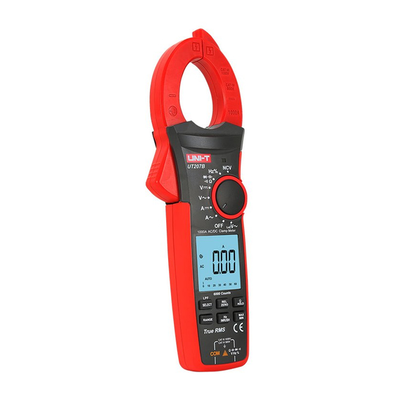
Page 5: External Structure
UT205E/UT206B/UT207B/UT208B User Manual UT205E/UT206B/UT207B/UT208B User Manual VI. LCD Display V. External Structure (Picture 1) (Picture 2, Picture 3, Picture 4) 9 10 1. Clamp jaws 2. Hand guard 3. LED indicator light 4. Jaw opening trigger Function dial 6. LCD display 7. - Page 6 UT205E/UT206B/UT207B/UT208B User Manual UT205E/UT206B/UT207B/UT208B User Manual 10 11 12 13 14 15 16 9 10 11 12 21 22 Picture 4 UT206B/UT208B Low battery Continuity test Inrush current measurement 16 17 18 High voltage Low impedance measurement Picture 3 UT207B...
- Page 7 Short press: enter the manual range mode and change the range. Long press: Long press or turn function dial to exit manual range mode. Only valid for ACV, LPF ACV, LoZ V~, DCV, ACA, DCA, CAP (UT205E only), and Ω.
-
Page 8: Specifications
±1.0% additional error in reading may be produced. Jaw opening: ------------------------ 42mm Battery: ------------------------------- 3×1.5V AAA Auto power off: ---------------------- 15 minutes (can be disabled) Dimensions: -------------------------- 272mm×81mm×43.5mm Weight (including batteries): ----- About 492g (UT205E/UT206B), 447g (UT207B/UT208B) - Page 9 2) Inrush Current ( Overload Overload Range Accuracy Range Accuracy Resolution Function Resolution Protection Protection 60.00A 0.01A ± (2.0%+5), for UT205E/UT206B Inrush current 60.00A 0.01A ± (10%+10) ± (2.0%+9), for UT207B/UT208B 600.0A 0.1A 1000A (ACA) 1000V DC/AC 1000A 600.0A 0.1A ±...
- Page 10 UT205E/UT206B/UT207B/UT208B User Manual UT205E/UT206B/UT207B/UT208B User Manual a) Add 4% when crest factor is 1~2 4 AC Voltage b) Add 5% when crest factor is 2~2.5 Range Accuracy c) Add 7% when crest factor is 2.5~3 Resolution Overload Protection The -3dB frequency of LPF is about 2.5kHz 6.000V...
- Page 11 UT205E/UT206B/UT207B/UT208B User Manual UT205E/UT206B/UT207B/UT208B User Manual 7) DC voltage ( 9) Continuity ( Range Accuracy Resolution Overload Protection Range Accuracy Resolution Overload Protection 600.0mV 0.1mV Open circuit: Resistance ± (0.8%+3) ≥70Ω, no beep 6.000V 0.001V 600.0Ω 0.1Ω 1000A Well-connected circuit: 60.00V...
-
Page 12: Operating Instructions
UT205E/UT206B/UT207B/UT208B User Manual UT205E/UT206B/UT207B/UT208B User Manual Measurement result = displayed value – capacitance of open-circuit test leads 14) Non-contact AC voltage sensing (NCV) For capacitance ≤1μF, it is recommended to use “REL” measurement mode. Range Accuracy Overload Protection Accuracy guarantee: 5%~100% of range Bring the NCV sensor (upper tip) close 12) Temperature (°C/°F) - Page 13 UT205E/UT206B/UT207B/UT208B User Manual UT205E/UT206B/UT207B/UT208B User Manual AC Current Measurement Note: 1) Turn the function dial to A~, , or position. The current measurement should be taken within 0°C~40°C. Do not suddenly 2) Press the trigger to open clamp jaws and fully enclose one conductor (only release the trigger, as the impact may change the reading for a short time.
- Page 14 UT205E/UT206B/UT207B/UT208B User Manual UT205E/UT206B/UT207B/UT208B User Manual 3. Measurement by Flexible Current Probe (Picture 6) Inrush Current Measurement 1) After connecting the flexible current probe, short press the RANGE button to select the proper range. 2) Long press the Hz/INRUSH button to enter the inrush current measurement mode.
- Page 15 UT205E/UT206B/UT207B/UT208B User Manual UT205E/UT206B/UT207B/UT208B User Manual 4. Related Measurement of AC Voltage and Voltage Frequency Measurement LPF ACV (Picture 7) 1) When the function dial is in the AC voltage, short press Hz or Hz/INRUSH button to enter the frequency measurement mode.
- Page 16 UT205E/UT206B/UT207B/UT208B User Manual UT205E/UT206B/UT207B/UT208B User Manual 5. DC Voltage Measurement (Picture 7) LoZ ACV Frequency Measurement 1) When the function dial is in the LoZ ACV position, short press the Hz/INRUSH 1) Insert the red test lead into the jack, and black test lead button to enter the frequency measurement mode.
- Page 17 UT205E/UT206B/UT207B/UT208B User Manual UT205E/UT206B/UT207B/UT208B User Manual When measuring resistance above 1MΩ, it is normal to take a few seconds to 7. Resistance Measurement (Picture 9) stablize reading. Use caution when working with voltage above AC 30Vrms, 42Vpeak or DC 60V.
- Page 18 UT205E/UT206B/UT207B/UT208B User Manual UT205E/UT206B/UT207B/UT208B User Manual 1) Insert the red test lead into the jack, and black into the 3) Connect the red probe with the diode anode, and black with the diode cathode. COM jack. 4) Read the approximate forward voltage of the diode on the display. For silicon...
- Page 19 UT205E/UT206B/UT207B/UT208B User Manual UT205E/UT206B/UT207B/UT208B User Manual 1) Turn the function dial to the °C°F position, and the LCD will display “OL”. 1) Insert the red test lead into the jack, and black into the Ambient temperature will be displayed if users short-circuit the test leads.
-
Page 20: Maintenance
UT205E/UT206B/UT207B/UT208B User Manual UT205E/UT206B/UT207B/UT208B User Manual X. Maintenance 1) Turn the function dial to the NCV position, and bring the NCV sensor close to Warning: Before opening the rear cover of the meter, remove the test leads the wire under test. - Page 21 UT205E/UT206B/UT207B/UT208B User Manual UT205E/UT206B/UT207B/UT208B User Manual...
Need help?
Do you have a question about the UT205E and is the answer not in the manual?
Questions and answers