Advertisement
Quick Links
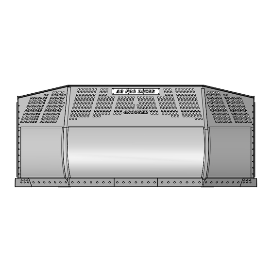
HD 19' U-Blade
Owner's Manual & Parts Book
Grouser Products
755 2nd Ave NW - West Fargo, ND 58078
Phone: 1-800-747-6182
Fax: 1-701-282-8131
E-mail: grouser@grouser.com
Website: www.grouser.com
PN: 63-43458
Serial Number: 10207014-Current
Purchase Date
Serial Number
Model Number
Tractor Model
Dealer
Date 11-3-2021
Advertisement

Related Manuals for Grouser Products HD 19 U-Blade


Summary of Contents for Grouser Products HD 19 U-Blade
- Page 1 HD 19’ U-Blade Owner’s Manual & Parts Book Purchase Date Grouser Products Serial Number 755 2nd Ave NW - West Fargo, ND 58078 Model Number Phone: 1-800-747-6182 Fax: 1-701-282-8131 Tractor Model E-mail: grouser@grouser.com Dealer Website: www.grouser.com PN: 63-43458 Serial Number: 10207014-Current...
- Page 2 Description Page Welcome To The Owner Safety Precautions, Torque Specifications & Pre-Installation Decals Maintenance & Lubrication Lift System Tractor Side Hydraulics Initial Startup Connecting and Disconnecting Tilt Plate Adjustment Lift Speed Control Installation Ag Pro 19’ U-Blade 12-13 No Angle - Hydraulic Tilt System 14-15 Hydraulic Multi-Coupler Maintenance 16-17...
- Page 3 A careful operator is the best operator. Most accidents can be avoided by observing certain precautions. To help prevent accidents, read and take the following precautions before operating this equipment. In addition, please follow all safety and operational instructions of your tractor manufacturer. The 19’...
- Page 4 PN: 27-2409 Left and Right Side HD 19U PN: 27-41686 WARNING Cancer and Reproductive Harm For more information go to www.P65Warnings.ca.gov 27-40962 PN: 27-40962 27-9503 PN: 27-9503 PN: 27-9505 Left and Right Side Left and Right Side...
- Page 5 Due to the harsh environment this equipment operates in, the following tasks should be performed every 10 hours or less. • Inspect all equipment before operation for existing or potential damage. • Lubricate all joints with high quality grease. See below for grease locations. •...
- Page 6 Some assembly of Lift System components is necessary. Follow the steps listed below. See diagram below for the correct hardware and orientation of parts. 1. Remove all pins and fasteners on each side of the undercarriage and set aside for later installation. 2.
-
Page 7: Tilt Function
8. Cycle both cylinders in and out 5 more times. 9. Check tractor oil level and fill if necessary. Run the blade through all the functions. If any function does not operate correctly, refer to corresponding section above and re- bleed. If problem still persists, call Grouser Products. - Page 8 ITEM QTY. PART NO. DESCRIPTION 16-812525 8mm x 1.25mm x 25mm Metric Hex Bolt Gr 10.9 25-19868 Multi-Coupling Plate - 2 Port - Fixed 25-19870 Multi-Coupling Plate - Male Coupler 25-19871 Multi-Coupling Plate - 2 Port - Cap 25-34342 Tappet Quick Coupler Male - Poppet Style 25-3453 Pioneer Dust Cap Tilt (Green) 25-3457...
- Page 9 ITEM QTY. PART NO. DESCRIPTION 34-12932 Cylinder Saddle 34-12933 Hose Clamp (worm drive - 4.5) 34-18888-GR -12 Green - Spiral Band 34-19494-OR -16 Orange - Spiral Band 35-12631-0810 81” x 1/2" -8JIC/-8JIC Abrasion Resistant Hose 35-12631-2930 293" (24.42”) x 1/2" -8JIC/-8JIC Abrasion Resistant Hose 35-12631-3200 320"...
- Page 10 5. Follow Steps #2-4 for the left tilt plates. THE INFORMATION CONTAINED IN THIS DRAWING IS THE SOLE PROPERTY OF GROUSER PRODUCTS INC ANY REPRODUCTION IN PART OR WHOLE WITHOUT THE WRITTEN PERMISSION OF GROUSER PRODUCTS INC IS PROHIBITED. 6. Once the tilt-way clearance is set, torque bolts to 640 ft-lbs.
- Page 12 ITEM NO. QTY. PART NO. DESCRIPTION 11-13485 Blade Stand 15-41965 19' U - Blade Weld 16-20124 1/2" x 1" Hex Bolt Gr 5 NC 16-20217 3/4" x 1-3/4" Hex Bolt Gr 5 NC 16-20558 1" x 2" Hex Bolt Gr 8 NC 16-20560 1"...
- Page 13 DWG. NO.: 41965-A...
- Page 14 Note: The cylinder part number is stamped on the base end of the cylinder opposite of the hydraulic ports. No. On Part No. Description Cylinder 23-34728 49-12272 Seal Kit 4” Bore x 2” Rod...
- Page 15 ITEM NO. QTY. PART NO. DESCRIPTION 16-20011 1/4" x 2-3/4" Hex Bolt Gr 5 NC 16-20128 1/2" x 2" NC Hex Bolt Gr. 5" 16-20130 1/2" x 2-1/2" Hex Bolt Gr 5 NC 16-20220 3/4" x 2-1/2" Hex Bolt Gr 5 NC 16-21065 3/8"...
- Page 16 Before Each Use: Fixed Half Mobile Half Disconnect the mobile half from the parking station and the cap from the fixed half. Check that there is no contamination (salt, sand, dirt, etc.): On the pins. Inside the cam. In the locking mechanism area. On the face of the plates and couplings.
- Page 17 Cleaning The Female Bushing: Cleaning The Male Interface Seal Make sure the coupling is securely fastened Make sure the coupling is securely fastened into the plate or place in a vice. into the plate or place in a vice. Using a blunt, non-marring tool, depress the Using a non-marring tool, depress the valve face until the seal is exposed.
- Page 18 Colored Lines = Quantity of Colored Spiral Bands Tilt Cylinder Tilt Cylinder Angle Cylinder Left Angle Cylinder Right Hydraulic Multi-Couplers Left Right Lift Cylinder Lift Cylinder Left Left Tilt Right Tilt Left Right Right Lift Up Lift Down Angle Angle Angle Angle Side Up Side Up...
- Page 19 Page Left Blank Intentionally...
-
Page 20: Warranty
If such equipment is found to be defective within two years, it is the obligation of Grouser Products under this warranty to repair or replace (exclusive of the cost of labor and transportation), any equipment or parts, in the judgment of Grouser Products to be defective in material or workmanship.
Need help?
Do you have a question about the HD 19 U-Blade and is the answer not in the manual?
Questions and answers