Advertisement
Quick Links
Advertisement

Related Manuals for Renogy REGO RCC60REGO-US


Summary of Contents for Renogy REGO RCC60REGO-US
- Page 1 REGO MPPT Solar Charge Controller VERSION A1 QUICK GUIDE...
-
Page 2: Table Of Contents
Contents Package Contents •••••••••••••••••••••••••••••••••••••••••••••••••••••••••••••••••••••••••••••••••••••••••••••••••••••••••••••••• Wiring Diagram •••••••••••••••••••••••••••••••••••••••••••••••••••••••••••••••••••••••••••••••••••••••••••••••••••••••••••••••••••••• Product Overview ••••••••••••••••••••••••••••••••••••••••••••••••••••••••••••••••••••••••••••••••••••••••••••••••••••••••••••••••• Installation •••••••••••••••••••••••••••••••••••••••••••••••••••••••••••••••••••••••••••••••••••••••••••••••••••••••••••••••••••••••••••••••• Communication ••••••••••••••••••••••••••••••••••••••••••••••••••••••••••••••••••••••••••••••••••••••••••••••••••••••••••••••••••••• Operation & Maintenance •••••••••••••••••••••••••••••••••••••••••••••••••••••••••••••••••••••••••••••••••••••••••••••••••... -
Page 3: Package Contents
Package Contents Renogy Temperature Solar Adapter Cable Quick Guide × 1 Sensor × 1 Mounting Screws × 4 ( Anderson PP75 to (Model: RTSCC) MC4 Adapter Cable ) REGO ST6.3x1.8x13mm MPPT Solar Charge Controller VERSION A0 QUICK GUIDE... -
Page 4: Wiring Diagram
REGO 12V 60A MPPT Solar Charge Controller. Please read the Quick Guide carefully before using. z Illustrations in the Quick Guide are for reference only. z For more detailed instructions, please refer to the user manual at renogy.com. z For additional support, please contact our customer service through renogy.com/contact-us/. -
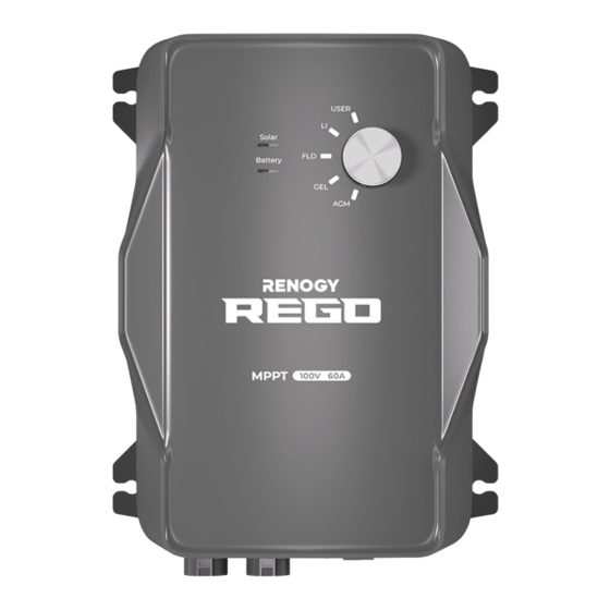
Page 5: Product Overview
Product Overview Part Part CAN Communication Ports Positive Battery Terminal Positive Solar Terminal Negative Battery Terminal Negative Solar Terminal Battery Temperature Sensor Port Battery Status Indicator Battery Voltage Sensor Port Solar Status Indicator Mounting Holes Battery Type Setting Knob z Please inspect the charge controller for any visible damage including cracks, dents, deformation, and other visible abnormalities before installation. -
Page 6: Installation
Installation Recommended Components Battery Scenario A: REGO Battery Kit REGO 12V 400Ah Lithium Iron Phosphate REGO 4 Ports 400A System Combiner Box Battery Battery Adapter Cable ( Anderson PP75 to Anderson 120 Adapter Cable ) Anderson PP75 Anderson 120 Battery Scenario B: Normal Battery Kit Battery Adapter Cables ( Anderson PP75 to Normal Battery with +/- Bolts Ring Terminal Adapter Cable ) - Page 7 Installation *Optional Accessories *Solar Panel In-line *Battery Voltage Sensor *Battery Fuse *Fuse Cable Fuse (Model: RVSCC) Required Tools Wrench (10mm) Wrench (14mm) Measuring Tape Insulation Tape...
- Page 8 Installation Mounting Location z Risk of explosion! Never install the charge controller in a sealed enclosure with flooded batteries! Do not install in a confined area where battery gases can accumulate. z Place the charge controller on a vertical surface protected from direct sunlight, high temperatures, and water.
- Page 9 Installation Charge Controller Wiring z Please refer to the user manual of the charge controller at renogy.com for the recommended wire gauge and length. z Please make sure that the connections of the Anderson connectors are tight and secure. REGO Battery Kit Normal Battery Kit 1.2.1...
- Page 10 Installation 1.2.5 1.2.6 For the Solar terminal, align the Solar Adapter Cable's Anderson Bind the Anderson PP75 connectors to the correct orientation and polarity. connectors by sliding the side grooves. Push the protective cover upwards. 1.2.7 Insert the Anderson connectors into the Solar terminal.
- Page 11 If positive/negative busbars are used to connect with the Renogy REGO Lithium Battery, please refer to the user manual of REGO MPPT Solar Charge Controller at renogy.com for more detailed instructions. Insert the Anderson 120...
- Page 12 For your safety, it is recommended to use a battery fuse. z Please refer to the user manual of the charge controller at renogy.com for the recommended fuse. Connect the positive Battery...
- Page 13 Once the solar panel wiring is completed correctly, the charger controller's Solar indicator lights up green. If the Solar indicator does not light up, please refer to the user manual of the charge controller at renogy.com for troubleshooting instructions. 1.4.3...
- Page 14 Installation For your safety, it is recommended to use a solar panel in-line fuse. z Please refer to the user manual of the charge controller at renogy.com for the recommended fuse. Insert the Solar Panel In- line Fuse between the Solar Adapter Cable and the solar panel's positive cable.
- Page 15 -20°C to 60°C or -4°F to 140°F) can charge the battery normally. z Do not use the temperature sensor on a LiFePO4 (LFP) battery which comes with a battery management system (BMS). z Please refer to the user manual of the charge controller at renogy.com for more matters needing attention. 1.6.1 1.6.2...
- Page 16 Installation *Voltage Sensor (Optional) The Battery Voltage Sensor is the perfect solution by providing an accurate battery voltage to the charge controller and allowing it to adjust the charging stage precisely resulting in overall extension of your battery life. z Identify the polarity (positive and negative) on the cables used for the batteries. A reverse polarity contact may damage the unit.
-
Page 17: Communication
If an RV-C bus is pre-installed in the RV, check the network wiring diagram provided by the RV manufacturer and follow the backbone topology for the RV-C communication connections. Refer to the user manual of the charge controller at renogy.com for more details. Daisy Chain Topology If the RV-C bus is not available, follow the daisy chain topology for the communication connections. - Page 18 Long-Range Monitoring If long-range communication and programming are required, connect the charge controller to Renogy ONE through Bluetooth or hard wire, and the Renogy ONE to the DC Home app through WiFi or cellular network. z Please make sure that the Renogy ONE is powered on before the connection.
- Page 19 ONE or the DC Home app. If the inter-device Wired connection communication is established (Daisy Chain Topology) with the backbone topology, connect the Renogy ONE to the RV-C bus. Contact the RV manufacturer for more details before the connection. If the inter-device communication is established...
-
Page 20: Operation & Maintenance
Ensure there is no any corrosion, insulation damage, or discoloration marks of overheating or burning. z Risk of electric shock! Make sure that all power is turned off before touching the terminals on the charge controller. z Please refer to the user manual of the charge controller at renogy.com for more details. - Page 21 FCC Statement This device complies with Part 15 of the FCC Rules. Operation is subject to the following two conditions: (1) This device may not cause harmful interference, and (2) This device must accept any interference received, including interference that may cause undesired operation.
- Page 22 Renogy Power PLUS Renogy Power Plus allows you to stay in the loop with upcoming solar energy innovations, share your experiences with your solar energy journey, and connect with like-minded people who are changing the world in the Renogy Power Plus community.
- Page 23 RENOGY.COM Visit renogy.com to find the User Manual or get more support via "Contact Us". Renogy reserves the right to change the contents of this manual without notice. Manufacturer: RENOGY New Energy Co.,Ltd Address: No.66, East Ningbo Road Room 624-625...
Need help?
Do you have a question about the REGO RCC60REGO-US and is the answer not in the manual?
Questions and answers