
Related Manuals for RGC VL100148


Summary of Contents for RGC VL100148
- Page 1 VL100148 VERTICAL LIFT INSTRUCTIONS REIMANN & GEORGER CORPORATION MARINE PRODUCTS BUFFALO, NY P/N 6112044 11/29/05...
- Page 2 PRE-LIFTING CHECKLIST The lift and related equipment must be thoroughly inspected prior to each use. Only those who have read and understood this entire manual and related equipment manuals are qualified to do this inspection. This checklist is to be used as a guideline in conjunction with the maintenance and inspection procedures outlined in this manual.
-
Page 3: Table Of Contents
VL 100148 Bundle 1 of 3......................23 7.1.2 VL 100148 Bundle 2 of 3......................23 7.1.3 VL 100148 Bundle 3 of 3......................23 VL Extension Legs ........................23 Bunk Bundle..........................23 Double Bunk Carton ........................23 R18HD W/ Mounting Hardware Carton ..................24 RGC MARINE PRODUCTS PHONE: (716) 895-1156... - Page 4 Frame Squaring Assembly/Table ....................10 Lower Diagonal Brace Assembly....................11 Cable Reeving & Adjustment......................13 Winch Cable Reeving........................14 Wire Rope Components ........................19 R18HD Winch..........................26 Spreader Tubes (AD & BC) ......................27 Load Tubes (AB & CD) ........................28 WARRANTY RGC MARINE PRODUCTS PHONE: (716) 895- 1156...
-
Page 5: Safety
WARNING: DO NOT OPERATE THIS LIFT WITHOUT STUDYING THIS ENTIRE MANUAL. FAILURE TO DO THIS CAN LEAD TO EQUIPMENT MISUSE WITH RESULTING DAMAGE AND/OR SERIOUS PERSONAL INJURY. CONTACT YOUR RGC® MARINE DEALER IF YOU HAVE ANY QUESTIONS. 1.2 SAFETY DEFINITIONS A safety message alerts you to potential hazards that could hurt you or others or cause property damage. -
Page 6: Installation Safety
WARNING: DO NOT STAND OR WALK ON THE PLATFORM WHILE IT IS IN ANY RAISED POSITION. THIS CAN CAUSE SERIOUS PERSONAL INJURY. 6. Do not allow anyone to swim or play under, near or on the lift at any time. 1.5 INSTALLATION SAFETY 1. -
Page 7: Safety When Raising The Boat
12. Never tamper with the winch mechanism. This can cause equipment damage. 13. Do not operate the lift under the influence of drugs, alcohol, or medication. 14. Never use the lift to hang or store any auxiliary equipment such as boating hardware. 1.6.2 Safety When Raising the Boat 1. -
Page 8: Specifications
2 SPECIFICATIONS 2.1 TECHNICAL DATA MODEL VL100148 Weight Capacity 10,000 lbs. Maximum Beam 147-1/2” Lifting Height 66” Overall Width (Including Feet) 163” Overall Length (Including Feet) 192” 16’ Full Length Double Bunks Std. S.S. Aircraft Cable Std. Polymer Sheaves Std. -
Page 9: Optional Equipment
2.3 OPTIONAL EQUIPMENT The following options are available which enable you to customize your lift for your particular operation. Installation instructions are provided as part of each option kit. 1. Acrylic Canopy— Boats tucked neatly under the heavy duty canopy are protected from the elements, reducing the need for boat coverings. -
Page 10: Installation And Setup
3 INSTALLATION AND SETUP 3.1 PRE-INSTALLATION CHECKS 1. Do not assemble the lift if any part shows any sign of damage. 2. Do not weld or otherwise modify the lift. Such alterations may weaken the structural integrity of the lift and void the warranty. -
Page 11: Vertical Leg Assembly
The lift may be placed on either side of your dock as shown in Figure 3-2. The winch is mounted onto vertical leg A. Figure 3-2. Lift / Dock Placement Options Place one bag of hardware at each corner. CAUTION: INSERT ALL BOLTS FROM THE INSIDE OF THE LIFT TO PREVENT DAMAGE TO YOUR BOAT. -
Page 12: Frame Side Assembly
3.4 FRAME SIDE ASSEMBLY 1. Refer to Figure 3-4. Fasten three long horizontal tubes between vertical legs A and D with hardware shown. DO NOT TIGHTEN. 2. Repeat step one for vertical legs B and C. 3. Lay the assembled sides down on the ground with the foot plates facing one another and aligned, about 15 feet apart. 4. -
Page 13: Mounting The Platform To The Frame
Figure 3-5. Platform Assembly – Top View 3.6 MOUNTING THE PLATFORM TO THE FRAME 1. Insure all platform fastenings are tight before mounting onto the frame. 2. Lift one of the frame sides and position it along a spreader tube side of the platform. 3. -
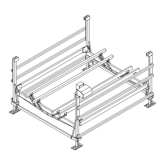
Page 14: Frame Squaring Assembly/Table
Figure 3-6. Frame Squaring Assembly / Table 3.7 MOUNTING THE LOWER DIAGONAL BRACES 1. Position a lower diagonal brace on the inside of vertical leg “B” as shown in Figure 3-7. Loosely fasten with hardware shown. 2. Position the opposite end along the short horizontal tube so that the tube is situated between the two holes located in the lower diagonal brace. -
Page 15: Mounting The Lower Diagonal Braces
CAUTION: THE FOUR LOWER DIAGONAL BRACES ARE MOUNTED ONLY TO THE TWO SHORT HORIZONTAL TUBES. NEVER TRY TO MOUNT THESE BRACES TO ANY OF THE LONG HORIZONTAL TUBES. 5. Plumb the frame by adjusting the verticals to achieve the same measured distance between them at both top and bottom. -
Page 16: Platform Reeving And Adjustment
3. Using a 1 1/8” open-end wrench, tighten the cable studs opposite the cable end loops in the following order. The following step numbers correspond to the step numbers shown in Figure 3-8. Step 1: Tighten down the nut to add tension to the B-C spreader tube cable. Step 2: Tighten down the nut to add tension to the A-D spreader tube cable. -
Page 17: Reeving The Winch & Vertical Leg "B" Sheave Block
3.9 REEVING THE WINCH & VERTICAL LEG “B” SHEAVE BLOCK 1. Refer to Figure 3-8. Reeve looped end of “AB Load Tube “ cable over vertical leg “B” sheave assembly by removing bolt and sheave/bushing assembly from block. Reassemble reeved sheave/bushing assembly back into block and fasten. -
Page 18: Winch Cable Reeving
Figure 3-9. Winch Cable Reeving 3.10 MOVING LIFT TO OPERATING POSITION 1. The following precautions must be observed when moving your lift for any reason: Be sure of your footing. b. Bend your knees and lift with your legs. Hold the lift section close to your body when lifting. 2. -
Page 19: Moving Lift To Operating Position
Frame Diagonal Measurement Diagram (Measure to Outside Corners) -
Page 20: Operation
4 OPERATION 4.1 BEFORE OPERATING THE LIFT 1. Read and know the instructions and insure that everyone understands the proper operating procedure. 2. When using a power drive, understand the use of all controls and connections provided with it. 3. Follow the Pre-Lifting Checklist before operating. 4. -
Page 21: Raising And Lowering The Platform
3. Lower the empty platform to repeat steps 1 and 2 with your boat on the lift. The power drive must turn counter- clockwise when lowering the platform. This counter-clockwise rotation allows the self-activating brake mechanism to stop the platform lowering as soon as the operator returns the switch to the off position. Make sure this brake mechanism is operative. -
Page 22: Inspection And Maintenance
5 INSPECTION AND MAINTENANCE 5.1 GENERAL MAINTENANCE RULES 1. Do not allow persons other than authorized service personnel to repair this equipment. 2. If slings are used, inspect them for deterioration. Replace them immediately if they are worn. 3. Do not weld or otherwise modify the lift. Such alterations may weaken the structural integrity of the lift and invalidate your warranty. -
Page 23: Annual Inspection
Figure 5-1 Wire Rope Components 5. Heat damage: Evidence of any heat damage caused by a torch or by contact with electrical wires. 6. Reduction of more than 1/64 inch from a nominal 5/16-inch or less diameter cable. Reduction of more than 1/32 inch from a nominal 3/8-inch to 1/2-inch diameter cable. -
Page 24: Storage Procedure
WARNING: AFTER EVERY WINCH MAINTENANCE, TEST THE WINCH MECHANISM AS DESCRIBED IN CHAPTER 4 BEFORE LETTING ANYONE USE THE LIFT. 5.5 STORAGE PROCEDURE 1. Position boat on platform so the lower unit of the motor is against the optional motor stop (if used). 2. -
Page 25: Troubleshooting
6 TROUBLESHOOTING The following chart is intended to assist with troubleshooting your vertical lift. While not all inclusive, the chart outlines the most common causes of a problem and the recommended course of action. SYMPTOM CAUSE AND CORRECTIVE ACTION Winch resists platform raising. Winch has been reeved incorrectly—winch must turn clockwise to raise platform. - Page 26 Boat shifts position when operating the lift. Boat is not properly secured on the lift—failure to properly secure boat can cause equipment damage and/or serious personal injury. Lowering operation triggers a “freewheeling” of Winch has been reeved incorrectly—winch must turn the winch.
-
Page 27: Parts Lists
Each reference number or letter in the following parts lists can be matched with the reference number or letter referred to in both the text and illustrations of Chapter 3, Installation and Setup. 7.1 VL100148 BOAT LIFT BUNDLES 7.1.1 #3610125 VL100148 Bundle 1 of 3 REF # PART # DESCRIPTION... -
Page 28: R18Hd W/ Mounting Hardware Carton
#3710310 R18HD W / MO UNTING HARDWARE CARTON REF # PART # DESCRIPTION R18HD (SEE SECTION 7.10) 3710405 R18HD MOUNTING HARDWARE Bag consisting of: 5806187 3/16 X 4-1/2 LG WRENCH L HANDLE 5896291 1/2 X 5-1/2 HHCS 5896400 1/2 SAE FLAT WASHER 5806244 1/2 SPLIT LOCK WASHER 5896379... - Page 29 DRUM CHAIN (#60 CHAIN) 3710630 #60 CHAIN CONNECTING LINK 6737805 GUARD TOP ASSY 3710905 GUARD BOTTOM 3710910 DECAL RGC OFFICIAL LOGO 6206974 DRUM SPOOL ASSY 3710620 SET SCREW 5806483 DECAL “WARNING” VL 6206970 WINCH MOUNT BAG OF BOLTS (see section 7.5)
-
Page 30: R18Hd Winch
Figure 7-1. R18HD Winch Assembly... -
Page 31: Spreader Tubes (Ad & Bc)
P/N 3610310 - VL 100148 (AD) SPREADER TUBE PARTS LIST P/N 3610315 - VL 100148 (BC) SPREADER TUBE PARTS LIST Figure 7-2. Spreader Tube Assembly... -
Page 32: Load Tubes (Ab & Cd)
P/N 3610320 VL 100148 (AB) LOAD TUBE PARTS LIST P/N 3610325 VL 100148 (CD) LOAD TUBE PARTS LIST Figure 7-3. Load Tube Assembly... - Page 33 Reimann & Georger Corporation Marine Products RGC Marine products, hereafter referred to as the “Manufacturer”, extends this limited warranty to the original purchaser of this product. The original purchaser, hereinafter referred to as the “Buyer”, is defined as the first legal owner of this product other than an authorized distributor or dealer who has bought the product from the Manufacturer for resale to the public.
- Page 34 E. NO LIABILITY IN EXCESS OF PURCHASE PRICE IN NO EVENT SHALL THE MANUFACTURER’S OBLIGATIONS UNDER THIS LIMITED WARRANTY EXCEED THE PURCHASE PRICE OF THE PRODUCT. F. NO EXTENSION OF STATUTE OF LIMITATIONS ANY REPAIRS PERFORMED UNDER EITHER OF THESE WARRANTIES SHALL NOT IN ANY WAY EXTEND THE TWO-YEAR AND FIFTEEN-YEAR STATUTES OF LIMITATIONS CONTAINED IN THIS LIMITED WARRANTY.
- Page 35 4. Damage under conditions caused by fire or accident, by abuse or negligence, by improper installation, by misuse, by incorrect operation, by “normal wear and tear”, by improper adjustment or alteration, by alterations not done by the Manufacturer, or by failure of product parts from such alterations. 5.
-
Page 36: Warranty
COMMERCIAL PRODUCT PROVISIONS II. ARTICLE II—COMMERCIAL PRODUCT PROVISIONS: THE FOLLOWING PROVISIONS SHALL BE APPLICABLE ONLY IF THIS PRODUCT IS BEING PURCHASED SOLELY FOR COMMERCIAL OR INDUSTRIAL USE. IF THIS PRODUCT IS BEING PURCHASED FOR PERSONAL, FAMILY OR HOUSEHOLD PURPOSES, THE PROVISIONS CONTAINED IN THIS ARTICLE II SHALL NOT BE APPLICABLE AND THE PROVISIONS CONTAINED IN ARTICLE I ABOVE SHALL APPLY. - Page 37 H. PROCEDURE FOR WARRANTY PERFORMANCE If the product fails to perform to the Manufacturer’s specifications, the Buyer must contact the dealer from whom the product was purchased. The Buyer must provide the dealer with the applicable model and serial numbers, the date of purchase, and the nature of the problem.
Need help?
Do you have a question about the VL100148 and is the answer not in the manual?
Questions and answers