Table of Contents
Advertisement
Advertisement
Table of Contents

Subscribe to Our Youtube Channel
Related Manuals for OSEE Lilmon 5


Summary of Contents for OSEE Lilmon 5
- Page 1 ON CAMERA Monitor User Manual...
- Page 3 Product Information Model: Lilmon 5 ON CAMERA Monitor Version: V010000 Release Date: May 8th, 2023 Company OSEE TECHNOLOGY LTD Contact Information OSEE TECHNOLOGY LTD. No.22 Building, No.68 zone, Beiqing Road, Haidian Address District, Beijing, China Post Code: 100094 Tel: (+86) 010-62434168...
-
Page 4: Contents
Contents The user manual applies to the following device types: Lilmon 5 The images and descriptions of Lilmon 5 are adopted as examples in the following document. Before reading the manual, please confirm the device type. -
Page 5: Table Of Contents
Contents Contents ..................... I Chapter 1 Overview .................. 1 Chapter 2 Safety ..................3 Chapter 3 Unpack and Installation ............7 Chapter 4 Start ..................11 4.1 Parts and Functions ..............11 4.2 Power On..................12 4.3 Supported Signal Format ............13 4.4 ZOOM&PAN .................. - Page 6 5.2.1 INPUT ..................22 5.2.2 Backlight ................... 23 5.2.3 Volume ..................24 5.2.4 Rotate ..................25 5.2.5 Status Bar ................. 27 5.2.6 Probe ..................28 5.2.7 Range ..................29 5.2.8 Matrix ..................29 5.2.9 Color ..................30 5.2.10 User LUT ................33 5.2.11 Info ..................
- Page 7 7.2 Dimensions .................. 87...
-
Page 9: Chapter 1 Overview
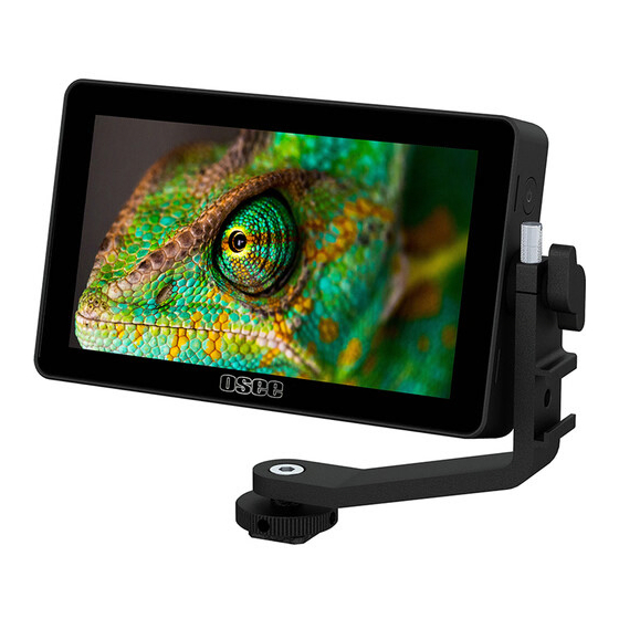
Overview Chapter 1 Overview Designed for photographers, v-loggers, and content creators, Lilmon 5 HDR monitor doubles the brightness of typical entry level monitors to 1000 nits and meets the minimum brightness requirement for outdoor shooting. It can seamlessly fit into a creative's workflow with its Swift OS touch screen, enhancing production efficiency. - Page 10 Support Image ZOOM of 1~4X ratios, and to pan the image in every direction Provide optional dummy battery adapters to output battery DC power to cameras Support on location calibration with x-rite probes and osee calibrator software...
-
Page 11: Chapter 2 Safety
Safety Chapter 2 Safety FCC Caution Any changes or modifications not expressly approved by the party responsible for compliance could void the user's authority to operate the equipment. This device complies with part 15 of the FCC Rules. Operation is subject to the following two conditions: (1) This device may not cause harmful interference, and (2) this device must accept any interference received, including interference that may cause undesired operation. - Page 12 Safety Device Install in accordance with the manufacturer's instructions. Do not touch the screen with sharp, metallic or abrasive objects. Do not make the freeze picture displaying on the screen time too long, otherwise, it will leave the afterimage on the screen. ...
- Page 13 Safety Do not damage the power cord, place the heavy objects on the power cord, stretch the power cord, or bend the power cord. Protect the power cord from being walked on or pinched, particularly at plugs, convenience receptacles, and the point where they exit from the unit.
-
Page 15: Chapter 3 Unpack And Installation
Chapter 3 Unpack and Installation Unpack: When unpacking the Lilmon 5 monitor, please verify that none of the components listed in Table 3.1 is damaged or missing. If there are any components missing, please contact your distributor or osee for it. - Page 16 Unpack and Installation Remove packing material including electrostatic-resistant screen protector. Retain these packing materials for future use. Connect required cables for signal input and output. Connect 6.2~16.8V DC power source through DC IN interface or power the monitor by NP-F battery. As a final step, turn on the device by single click the power button located on the right side of the unit.
- Page 17 Unpack and Installation Figure 3-2 Connect BATT OUT to Dummy Battery Mounting Installation: There are two 1/4 inch screw holes with anti-rotation pin holes on the monitor for installing various types of mountings, as shown in the illustration below. Screw the mounting into the screw hole, and fasten it tightly.
- Page 18 Unpack and Installation Figure 3-3 Positions for Mounting Installation Accessory Installation: Connect a standard signal cable to the relevant input port.
-
Page 19: Chapter 4 Start
Features Chapter 4 Features 4.1 Parts and Functions The parts of Lilmon 5 are shown as below, there are various input and output interfaces for Lilmon 5 monitor, as shown in Figure 4.1-1. Figure 4.1-1 Parts in Rear Panel No. Connector... - Page 20 Features No. Connector Description Power Click the power button to power on; and long Button press again for 3s to power off Card Insert an SD card to load user LUTs or update Slot firmware HDMI HDMI input and output interface, supports In&Out HDCP, compatible DVI1.0, HDMI 1.4 Battery Slot Support Sony NP-F Battery, 6.2 ~...
-
Page 21: Power On
Two-fingers zoom in&out: use two-fingers swipe to zoom in or out, use one-finger swipe to pan the image when it’s zoomed. 4.3 Power On The power button is on the right side of Lilmon 5. - Page 22 Figure 4.3-1 Power Button Power Method There are two methods for powering Lilmon 5 as below: Method 1: Power by battery There is a built-in battery slot at the rear panel of the monitor. It supports SONY NP-F series batteries(5V ~ 8.4V).
- Page 23 Features screen is locked. Then click again to unlock the screen. Once the screen has been locked, it can’t allow any operation until being unlocked by clicking the power button again. Tap the screen, it will display a screen lock prompt on the screen, as shown in Figure 4.3-2.
- Page 24 Features ZOOM Zoom in: Place two fingers on the screen to stretch out, thus to zoom the screen image in. Zoom out: Place two fingers on the screen to pinch in, thus to zoom the screen image out. Tap on screen to display the zoom frame, as shown in Figure 4.4-1: Figure 4.4-1 Zoom Frame The zoom ratio is displayed in the title bar of the zoom frame.
- Page 25 Features Figure 4.4-2 Zoom Frame Pan Starting Position There is a small rectangle in the zoom frame, as shown in Figure 4.4-3, it represents the current full screen image on the monitor, you can judge where this area is in the original image. Tap and drag it to move the starting position of the enlarged image in current zoom ratio.
-
Page 26: Zoom&Pan
Features Figure 4.4-4 Zoom 4X Editing Mode Move around Drag the small rectangle in the zoom frame left, right, up or down to pan the starting position of the image. Original Image Pinch in on screen until the zoom ratio is 1X, it will recover and display the original image, thus to exit zoom mode and close the zoom frame. - Page 27 Features Signal Format HDMI √ 2160P25 √ 2160P24/23.98 √ 1080P60/59.94 √ 1080P50 √ 1080P 1080P30/29.97 √ 1080P25 √ 1080P24/23.98 √ 1080I60/59.94 1080I √ 1080I50 √ 720P60/59.94 720P √ 720P50 √ 576P50 576P50 √ 480P60 480P60...
-
Page 29: Chapter 5 Swift Os Operation
Monitor Settings Chapter 5 Monitor Settings This chapter describes the structure and functionality of the monitor settings, and introduces how to modify and customize them. Monitor menu contains the settings on input, backlight, volume, display rotate, status bar, LUTs, anamorphic, language, color management and so on, as shown in Figure 5-1. -
Page 30: Monitor Settings
Monitor Settings Tap on the monitor settings button to display monitor settings menu on screen, as shown in Figure 5.1-1: Figure 5.1-1 Structure of Monitor Settings Menu The menu bar is divided into two parts: Level 1 Menu and Level 2 Menu. Follow the instructions below: Level 1 Menu for Monitor Settings It lists all items for monitor settings on the bottom of the screen, including... -
Page 31: Backlight
INPUT HDMI Select input signal source The INPUT menu of Lilmon 5 can’t be modified since it only has one input type. 5.2.2 Backlight The Backlight menu item is used to adjust the backlight of the screen. The menu item is as shown in Figure 5.2-1: Figure 5.2-1 Backlight Menu... -
Page 32: Volume
Monitor Settings Figure 5.2-2 Adjusting Backlight 5.2.3 Volume The Volume menu is used to adjust volume, as shown in Figure 5.2-3: Figure 5.2-3 Volume Menu Table 5.2-3 Description of Volume Item Default Domain Range Description 0~31 VOLUME Adjust the volume ... -
Page 33: Rotate
Monitor Settings area of the screen to increase or decrease the volume. As shown in Figure 5.2-4, swipe up to increase volume, and swipe down to decrease it, the range is 0~31. Figure 5.2-4 Volume Menu 5.2.4 Rotate The Rotate menu is used for rotation and mirror, as shown in Figure 5.2-5: Figure 5.2-5 Rotate Menu Table 5.2-4 Description of Rotate Menu Item... - Page 34 Monitor Settings Item Default Domain Range Description Image Only rotate the image in 0/180 Rotate vertical direction Image Mirror image Off/On Mirror horizontal direction Display Rotate Set Screen Rotate item to be 180, 0 or Auto, the input image will reverse vertically with the menus, as shown in Figure 5.2-6: Figure 5.2-6 Vertical Rotate ...
-
Page 35: Status Bar
Monitor Settings Figure 5.2-7 Horizontal Rotate 5.2.5 Status Bar The Status Bar menu is used to set the display options of status bar, as shown in Figure 5.2-8: Figure 5.2-8 Status Bar Menu Table 5.2-5 Description of Status Bar Item Default Domain Range Description Enable/disable/only show... -
Page 36: Probe
Monitor Settings Figure 5.2-9 Status Bar INPUT FORMAT The Signal Format usually displays the following situations: UNKNOWN: appears if an unsupported signal is input. No Signal: appears if no signal is detected. Normal: the signal format is displayed as HDMI 1080i59.94, etc. when the input is supported by the monitor. -
Page 37: Range
Monitor Settings 5.2.7 Range The Range menu item is used to set the Input Range as shown in Figure 5.2-11: Figure 5.2-11 Range Menu Table 5.2-7 Description of Range Item Default Domain Range Description Refers to the range of values your video is encoded within, if you don’t know the Options... -
Page 38: Color
Monitor Settings Item Default Domain Range Description Define color AUTO/ matrix standard the Rec 601(SD)/ Options AUTO incoming signal Rec 709(HD)/ using, if unsure, just Rec 2020(UHD) select Auto 5.2.9 Color Set the items of Color according to the video format you are shooting with, so the monitor can display, interpret and analyse it correctly, as shown in Figure 5.2-13: Figure 5.2-13 Color Menu... - Page 39 Monitor Settings Gamut Refer to Table 5.2-10 Set Gamut Color Profile The monitor is equipped with versatile camera profiles for different requirements. We provide the following color profiles: Set Style and Format according to a camera model, then choose Gamma and Gamut, as shown in Table 5.2-10: Figure 5.2-14 Color Settings ...
- Page 40 Monitor Settings PROFILE GAMMA GAMUT EI500 EI640 EI800 EI1000 EI1280 EI1600 BMD Film BMD 4K Film, BMD 4.6K Film, BMD BMD 4K Film Pocket 6K Film BMD 4.6K Film C LOG Rec.709, Canon Cinema, Rec 2100, Canon C LOG2 DCI-P3, DCI-P3+ C LOG3 FUJI F-LOG...
-
Page 41: User Lut
Monitor Settings The preset color profiles are constantly under development. Please confirm your LOG settings before shooting videos, then activate LOOK tool in a MySet to monitor your image. 5.2.10 User LUT The User LUT menu item is used to load User LUT, as shown in Figure 5.2-15: Figure 5.2-15 User LUT Menu Table 5.2-11 Description of User LUT... - Page 42 Monitor Settings Figure 5.2-16 LUT List Tap one user LUT ID in the list to choose it as the designated LUT slot. Then, it will pop up a prompt for reminding you overwriting operation for LUT file, as shown in Figure 5.2-17, tap Confirm button and then select the target LUT from SD card in the next popup window, as shown in Figure 5.2-18, the file should be a LUT file with “.cube”...
- Page 43 Monitor Settings Figure 5.2-18 USER LUT Directory For example: Load a LUT file to LUT1, tap LUT1 in the LUT list, it will pop up a series of directories for navigating to the designated LUT file, as shown in Figure 5.2-17, then choose a target USER LUT to be uploaded from SD card, it will prompt the writing status, as shown in Figure 5.2-19, then it will prompt file writing complete after file loading.
- Page 44 Refer to “6.1.4 Look Tool” for the details about applying the 3D LUT file. Make sure your SD card is FAT32 format and under 16G, otherwise, it might not be supported by this monitor. Lilmon 5 supports color management software CalMAN currently, the...
-
Page 45: Info
Monitor Settings customized 3D LUT profiles (*.cube) produced by these software could be loaded to SD card by a control computer. If detecting no SD card during the operation, it will prompt ”No Media”; if any other wrong happened, it will pop up the relevant prompt, please check it according to the prompt. - Page 46 Monitor Settings Figure 5.2-24 Factory Reset Table 5.2-13 Description of Factory Reset Item Description Factory Reset Revert the factory settings FACTORY RESET Tap Reset Factory Reset to initialize the settings to default values, as shown in Figure 5.2-25: Figure 5.2-25 Factory Reset It will pop up a prompt, as shown in Figure 5.2-26, tap Confirm button to confirm the reset operation.
- Page 47 Monitor Settings Figure 5.2-26 Prompt for Factory Reset Figure 5.2-27 Boot Screen FIRMWARE UPDATE Insert an SD card with latest firmware file(s) in root directory, power on the device and it will upgrade automatically, then after successfully upgraded, it will prompt as shown in Figure 5.2-28:...
-
Page 48: Support
No power cut off during firmware upgrading and resetting, or the monitor will be dead. 5.2.13 Support The Support menu provides following supports to our customers: osee’s website’s QR Code, website address and e-mail, as shown in Figure 5.2-29. For any questions, please contact us by above contact ways. - Page 49 Monitor Settings...
-
Page 51: Chapter 6 Mysets And Tools
6.1 Tools Settings You can create customized MySet pages with different features and tools in Lilmon 5. In a MySet, tap the PLUS icon in tool bar to Add, Delete a TOOL. Tap on the screen, the tool bar is displayed at the bottom of the screen, as shown in Figure 6.1-1. - Page 52 MySets and Tools Figure 6.1-2 Tool List for A MySet Table 6.1-1 Tool Icons Tool Icon Tool Icon Aspect Marker Vector Safe Marker Histogram Center Marker Focus Assist Crosshatch Peaking Anamorphic Look False Color Multi-scopes Zebra Audio Meter Waveform After adding a tool to the tool bar of a MySet, you can edit the tool’s attributes by clicking the ARROW icon and its tool settings menu will pop up, as shown in Figure 6.1-3:...
-
Page 53: Frame Tools
MySets and Tools Figure 6.1-3 Tool Settings Menu It will introduce the tools and their attributes in the following section, please refer to “6.2 MySets and Tools Operations” for the details about tools operation. 6.1.1 Frame Tools Frame tools assist to set viewing frame, including aspect area, safe area, center and crosshatch. - Page 54 MySets and Tools Tool Items Default Domain Range Description 4:5/1:1/ the marker 4:3 (SD TV)/ 1.375:1(Cinema 16:9 (HD TV)/ 1.85:1(Cinema)/ 2.37:1(Cinema)/ CUSTOM Set the width of the matte Custom 3:1 ~1:3 area in CUSTOM mode, Ratio the step is 0.02 Set the transparency of Opacity the matte darken area...
- Page 55 MySets and Tools Tool Items Default Domain Range Description Enable magnify to draw the image full screen after de-squeezing the image Magnify OFF/ON with selected anamorphic ratio, cut the Anamorp part which extend outside the screen 1.33X/1.4X/ Ratio 1.33X 1.5X/1.6X/1.8X/ Set the anamorphic ratio 1.9X/2X Marker...
- Page 56 MySets and Tools Marker Illustration Description composition of a picture. Set Anamorphic Ratio This feature enables you to de-squeeze signals coming from camera utilizing anamorphic lenses that may not have a built-in de-squeeze feature of their own. The valid area which will fill the screen is controlled by the ratio selection, tap Anamorphic...
-
Page 57: Expose Tools
Figure 6.1-5: Figure 6.1-5 MAGNIFY 6.1.2 Exposure Tools Lilmon 5 provides exposure tools including false color, zebra, waveform, vector and histogram, as shown in Figure 6.1-6: Figure 6.1-6 Expose Tools Table 6.1-4 Description of Expose Tools... - Page 58 MySets and Tools Domain Tool Items Default Description Range Follow Camera/ Set the type of the false color Style Spectrum Spectrum/ display Custom When Style is Custom, set the Black Clip 3%CV 1-99%CV threshold of black clip, step is When Style is Custom, set the Near Black 4%CV 2-100%CV threshold of near black, step is...
- Page 59 MySets and Tools Domain Tool Items Default Description Range Set Tone 1’s maximum code Tone1 4%CV 1-100%CV value for detecting areas of a certain luminance range Set Tone 2’s minimum code Tone2 MIN 97%CV 0-99%CV value for detecting areas of a certain luminance range Set Tone 2’s maximum code Tone2...
- Page 60 False Color tool. When Style is set to Spectrum, the monitor will display a standard spectrum false color; when Style is set to Follow Camera, Lilmon 5 will display a calculated false color according to the Color settings in Monitor Settings, the indicator at the middle...
- Page 61 MySets and Tools Spectrum, as shown in Figure 6.1-7: Figure 6.1-7 Comparison Mode-Original Image and Normal Mode Image The Zebra tool is incompatible with the False Color tool. That is, enable the Zebra tool, the False Color tool will be disabled automatically, and enable the False Color tool, the Zebra tool will be disabled automatically.
- Page 62 MySets and Tools Figure 6.1-8 Illustration for ZEBRA Function Waveform Waveform displays the luminance level of the input signal on a graph, matching with the image from left to right. Waveform Size Set WaveformSize item to adjust the size of the waveform, there are three kinds of sizes for waveform: ...
- Page 63 MySets and Tools waveform as LUMA, RGB, Parade, as shown in Figure 6.1-9: Figure 6.1-9 LUMA and RGB and PARADE Waveform Vector A vectorscope contains markings that indicate the degree of hue and saturation in an image. Figure 6.1-10 Vector Histogram Histogram assists in judging the distribution of luminance in an image.
- Page 64 MySets and Tools Figure 6.1-11 RGB and LUMA Histogram Position There are 4 positions for displaying the histogram, waveform and vector scope on the screen, as shown in Table 6.1-5 and Figure 6.1-12. Move them through the Position item. Table 6.1-5 Position Settings Locations Top Right Top Left...
- Page 65 MySets and Tools Opacity There are 4 degrees of opacity for display the histogram, waveform and vectorscope on the screen. Set the transparency through the Opacity item. 100%: when opacity set to 100%, the assistant element (histogram, waveform vectorscope) opaque, transparent.
-
Page 66: Focus Tools
MySets and Tools Figure 6.1-13 Different Opacity for Histogram 6.1.3 Focus Tools Focus tools provide focus assist and peaking function. Set display color, sensitivity and display type for focus assist, and set intensity for peaking detecting. Figure 6.1-14 Focus Tools Table 6.1-6 Description of Focus Tools Domain Tool... - Page 67 MySets and Tools Domain Tool Items Default Description Range White Select the color of the focus /Red assist edge. The intensified Color /Green edges highlight in selected /Blue color. Set the edge difference value between the edges in an Focus image, and take this value as 1~10 Sensitivity...
-
Page 68: Look Tool
MySets and Tools B&W Mode: Set Focus Assist Background item as B&W, the image is in black and white mode, that is removing all colors and only leaving the luminance data of the signal. Figure 6.1-15 Illustration for FOCUS ASSIST Function Figure 6.1-16 Illustration for FOCUS ASSIST Function 6.1.4 Look Tool Look tool provides USER LUT and DE-LOG mode to current MySet, as... - Page 69 As the precondition for de-log switch, set Color item in monitor settings to select a camera profile(Style, Format, Gamma and Gamut) item according to your camera connected with Lilmon 5, the settings pane is as shown in Figure 6.1-18: Figure 6.1-18 COLOR MANAGEMENT SETTINGS...
- Page 70 MySets and Tools Figure 6.1-19 DE-LOG SETTINGS Refer to “5.2.9 Color” for the details of the COLOR settings and versatile color profiles. User LUT File If you want to apply a USER LUT tool to current signal displayed on screen, you should load the USER LUT in monitor settings at first.
- Page 71 MySets and Tools Figure 6.1-21 Calibration USER LUT Directory It will prompt file write complete after file loading. Then, you can see the profile name is on the left side of the current LUT ID in the list. You can load up to 10 USER LUTs into the device, for example as shown in Figure 6.1-22.
-
Page 72: Analysis Tool
Then, you can adjust intensity of this LUT effectiveness on screen through the Intensity item. Lilmon 5 supports color management software CalMAN, the customized 3D LUT profiles (*.cube) produced by these software could be loaded to SD card by a control computer. - Page 73 MySets and Tools Tool Items Default Domain Range Description Vector X1/X2 Set the gain of vector Histogram LUMA LUMA/RGB Set the type of the histogram Set the density of audio meter, 25%/50% Density waveform, histogram 75%/100% vector displayed on screen This tool puts multiple analysis charts and the image together.
-
Page 74: Meter Tool
MySets and Tools 6.1.6 Meter Tool Meter tool provides adding audio meter to current MySet, as shown in Figure 6.1-27: Figure 6.1-27 Meter Tools Table 6.1-9 Description of Meter Tools Domain Tool Items Default Description Range Bot Left/ Set the position of the Position Bot Left Bot Right... -
Page 75: Mysets And Tools Operations
It will introduce how to edit MySet and configure tools in this section. 6.2.1 MySet Preview We support 8 MySets in Lilmon 5, you can customize each MySet with various tools as your requirement, and switch among these MySets in MySet preview page. - Page 76 MySets and Tools numeric of MySet is displayed at the bottom of each MySet thumbnail, and the tool thumbnails for each MySet are tiled on the MySet thumbnail, as shown in Figure 6.2-2: Switch MySets Tap on the thumbnail to switch among these MySets, and the name of current MySet will be displayed in the top right-center of the status bar.
-
Page 77: Clear A Myset
MySets and Tools operation bar, as shown in Figure 6.2-2. Lilmon 5 supports up to 8 customized MySets. The 8 MySets exist by default and undeletable. Factory has 3 MySets (frame, exposure, focus) preset, you can edit them to your preferences. - Page 78 MySets and Tools It will display the delete page, as shown in Figure 6.2-4. There will be DELETE button at the bottom of each MySet thumbnail. Figure 6.2-4 Delete a MySet Tap one MySet thumbnail to delete it, and there will be a prompt for deletion, as shown in Figure 6.2-5.
-
Page 79: Add A Tool
MySets and Tools Figure 6.2-5 Prompt for Delete a MySet 6.2.3 Add a Tool In a MySet, add some tools to assist in composition, for example, add a marker, waveform, histogram or audio meter, etc. Each MySet supports up to 8 MySet tools. ... - Page 80 MySets and Tools Figure 6.2-6 Add a New Tool There are 15 tools offered in this device, as shown in Figure 6.2-7, including Aspect marker, Safe marker, Center marker, Crosshatch, Anamorphic, False Color, Zebra, Waveform, Vector, Histogram, Focus Assist, Peaking, Look, Multi-scopes and Audio meter. Figure 6.2-7 Tools Menu for MySet Tap add button to display the tool list above the operation bar, as...
- Page 81 MySets and Tools Figure 6.2-8 Tool List For example: Add histogram to Tool Bar Step 1 Load Tool List Tap add button to display the tool list above the operation bar, as shown in Figure 6.2-9:...
- Page 82 MySets and Tools Figure 6.2-9 Add a Tool Step 2 Add HISTORGRAM Tool Swipe left until Historgram item shows up, as shown in Figure 6.2-10. Tap on Historgram to confirm the selection, the Historgram tool icon will be added into the tool bar, as shown in Figure 6.2-11: Figure 6.2-10 Choose Histogram Tool Figure 6.2-11 Histogram in the Tool Bar...
-
Page 83: Load/Close Tool Bar
MySets and Tools Continue to add other tools for a MySet, and you can add up to 8 tools in a MySet. Tap close button to close the tool list. 6.2.4 Load/Close Tool Bar In a MySet, tap the screen to load or close the tool bar. The instructions are as below: ... -
Page 84: Turn On/Off A Tool
MySets and Tools 6.2.5 Turn ON/OFF a Tool In tool bar, follow the instructions below to turn on or off a tool swiftly: Turn on a Tool After adding a tool, tap the tool button to turn it on in tool bar, the icon will turn from gray to highlight green. -
Page 85: Tool Settings
MySets and Tools Figure 6.2-14 Turn off a Tool The tool could only be turned on or off in the tool bar. 6.2.6 Tool Settings Add tools for a MySet through tool list, then, set a tool’s attributes by the tool settings bar. - Page 86 MySets and Tools Figure 6.2-15 Tool Settings Bar The default settings displayed in the tool settings bar are the attributes of the first tool in current tool bar. Tap the tool you want to configure to switch to its attributes.Take the histogram for example. For example: Edit histogram in a MySet.
- Page 87 MySets and Tools Figure 6.2-16 Activate Histogram Step 2 Load the Tool Settings Bar In a MySet, tap the upward arrow in tool bar after adding the histogram tool, as shown in Figure 6.2-17: Figure 6.2-17 Expand Arrow...
- Page 88 MySets and Tools Then load the tool settings bar above the tool bar, the default attributes are for the first tool in the tool bar, here is Focus Assist, as shown in Figure 6.2-18: Figure 6.2-18 Tool Settings Bar Step 3 Switch Tool Settings for the Target Tool Tap HISTOGRAM tool in the tool bar, and the tool settings will switch to the contents for histogram, as shown in Figure 6.2-19.
-
Page 89: Delete A Tool
MySets and Tools Figure 6.2-19 Tool Settings Bar-HISTOGRAM Close Tool Settings Tap the downward arrow to close the tool settings bar. The parameters of the tool could not be modified until selecting the tool’s settings. 6.2.7 Delete a Tool In a MySet, delete tool by the following two methods: Method 1: Delete a tool in the tool list Tap add... - Page 90 MySets and Tools Figure 6.2-20 Delete a Tool Tap the tool which you want to delete, and it will pop up a prompt to confirm the deletion, as shown in Figure 6.2-21, tap on OK button to confirm, then the tool will be deleted from its tool bar. Figure 6.2-21 Prompt for Deleting a Tool...
- Page 91 MySets and Tools Method 2: Delete tool in the MySet preview page Tap MySet preview button at the right most in the operation bar at the bottom of the screen to display the MySet preview page, then you can delete all tools in the selected MySet by tapping the trash button.
-
Page 93: Chapter 7 Specifications
Specifications Chapter 7 Specifications 7.1 Product detailed information Specification Values Model Lilmon 5 Display 5.5” Dimension Aspect Ratio 16:9 178 ° (H)*178 ° (V) Viewing Angle (HxV) 1920 × 1080 Resolution Contrast 1000:1 Brightness 1000nits Input Signal Formats 4KP30/29.97/25/24/23.98 2160P30/29.97/25/24/23.98 1080P ( 60/59.94/50/30/29.97/25/24/23.98) - Page 94 Specifications Specification Values Remote 2.5mm Jack for color calibration Power DC IN 6.2 ~ 16.8V Input Voltage Sony NP-F Series (6.2 ~ 16.8V) Battery Types BATT OUT (5 ~ 8.4VDC) Battery Output Consumption 8.1W Environmental Operating 0 ° C~40 ° C Temperature Dimensions(Bare 144.0(mm) ×...
- Page 95 Color Profiles for Cameras LUT Loaded via SD Card Firmware Upgrading Language *The unit about the appearance attributes in above table is mm. 7.2 Dimensions The description of Lilmon 5 dimensions are as shown in the following figures (Unit: mm):...
- Page 96 Specifications Figure 7.2-1 Front View(Unit: mm) Figure 7.2-2 Back View(Unit: mm)
- Page 97 Specifications Figure 7.2-3 Side View(Unit: mm) Figure 7.2-4 Top View (Unit: mm) Specifications are subject to change without notice. ------------------No Text Below------------------...
- Page 99 FOR MORE INFORMATION PLEASE VISIT: http://www.osee-tech.com/ OSEE TECHNOLOGY LTD. Address: No.22 Building, No.68 zone, Beiqing Road, Haidian District, Beijing, China Tel: (+86) 010-62434168 Fax: (+86) 010-62434169...
Need help?
Do you have a question about the Lilmon 5 and is the answer not in the manual?
Questions and answers