Advertisement
Quick Links
Advertisement

Related Manuals for TMG TMG-ST3040-1.0


Summary of Contents for TMG TMG-ST3040-1.0
- Page 1 W W W . T M G I N D U S T R I A L . C O M P 0 / 2 0 T o l l F r e e : 1 - 8 7 7 - 7 6 1 - 2 8 1 9...
-
Page 2: Main Specifications
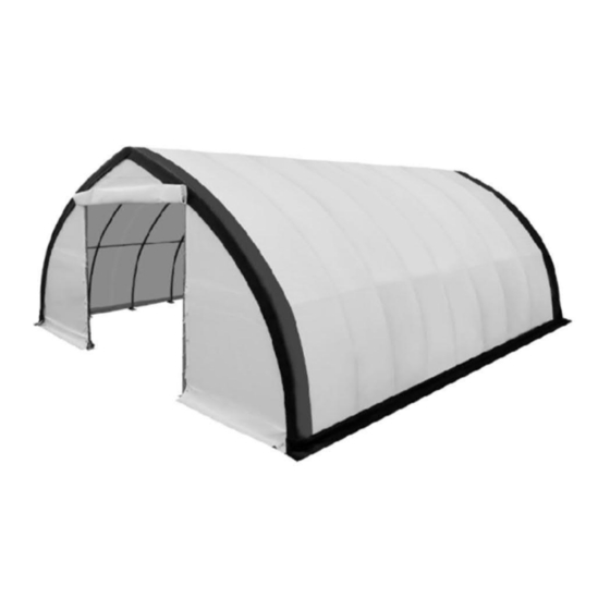
Main Specifications : - Overall assembled size : W9.14 x L12 x H4.57 (m) / 30 x 39.3 x 15(ft) - Front and back roll up door : W3.65 x H3.3 (m) / 11.97 x 10.8(ft) Prior to assembly Please read the instructions carefully before installation. It is important to follow your local safety regulations and industry standards during installation. - Page 3 Keep the building surroundings clear at all times. TMG-ST3040-1.0 Part List Parts Graphical Description Length code φ58xL2290mm Peak arch tube Upper rafter tube φ58xL2866mm (middle truss) Upper rafter tube φ58xL2866mm (front and rear truss) Lower rafter tube φ58xL2800mm (middle truss) Lower rafter tube φ58xL2800mm...
- Page 4 Door frame lower tube φ58xL1920mm (front and rear truss) Door frame upper tube φ58xL1800mm (front and rear truss) Door frame middle tube φ42xL2090mm (front and rear truss) φ42xL2480mm Ceiling cross bar Rope pulley W35xL130mm Rope pulley W35xL85mm Bottom tension bar φ32xL2560mm (front and rear cover) Diagonal bracing bar...
- Page 5 Top cover Front and rear cover panel φ8x160m Braided rope 1 bundle Tension band W38xL800mm Scratch resistant tape L10m W W W . T M G I N D U S T R I A L . C O M P 4 / 2 0 T o l l F r e e : 1 - 8 7 7 - 7 6 1 - 2 8 1 9...
- Page 6 Mark the ground in the final building location with a line showing the positions of base plates, front, and rear doors. All lines should be drawn from center to center of all baseplate tubes. Baseplates : all baseplates must be installed firmly with expansion bolts (#16) on this step (figure 1).
- Page 7 Step 2 : Assemble all trusses The building includes 9 trusses : (1) Front truss (1st truss), (1) rear truss (9th truss), and (7) middle trusses. The front and rear trusses are installed with the fabric panel (#23). Both front and rear truss include the following parts.
- Page 8 The (7) middle trusses include the following parts. Connect all tubes with bolt (#18) (refer to figure 3). - (1x7) Peak arch tube (#1) - (2x7) Upper rafter tube (#2) - (2x7) Lower rafter tube (#3) - (1x7) Ceiling cross bar (#11) - (2x7) Hex bolt (#19) - (8x7) Half round head bolt (#18) Figure 3...
- Page 9 Lay down all (9) trusses on the ground when the assembly is all completed and before moving to next step, and then wrap (#26) around the sharp points of the joint to avoid friction between the fabric and the interface, resulting in fabric damage (figure 4).
- Page 10 Step 3 : Put up the front (1 ) truss Use of a crane or forklift is recommended, otherwise a team can use ropes to lift the trusses, but you have to make sure it is safe, and have enough manpower.We recommend 3 to 5 people to pull the truss up from different directions.
- Page 11 Step 4 : Put up the rest trusses Install (#4) horizontal pull pipe at the marked position on the main pipe. Connect (#4) and #4A) together with bolts (#17) and firmly fix all bolts on each span before moving to the next truss (figure 6).
- Page 12 Figure 6-2 W W W . T M G I N D U S T R I A L . C O M P 1 1 / 2 0 T o l l F r e e : 1 - 8 7 7 - 7 6 1 - 2 8 1 9...
- Page 13 Step 5 : Install the diagonal bracing bars (#13) Connect diagonal bracing bar (#13) on the first and last span to lower rafter tube (#3A and #3) with tube clamp (#13A), use bolt (#19)(figure 7). Parts used in this step : - (2x2) Diagonal bracing bars (#13) - (4x2) Tube clamps (#13A) - (4x2) Bolts (#19A)
- Page 14 Step 6 : Install the remaining parts on the front and rear trusses (figure 8) Install rope pulley (#11A) on the right, (#11B) on the left as shown. - (2x2) Door frame lower tube (#8) - (2x2) Door frame upper tube (#9) - (2x2) Door frame middle tube (#10) - (1x2) Rope pulley (#11A) - (1x2) Rope pulley (#11B)
- Page 15 Step 7 : Install front and rear cover panel The door cover must be zipped. Use rope (#24) to lift up the front cover (#23) from the center grommet and tie it firm to the truss tube and spread toward both sides through each grommet along the tube.
- Page 16 The rope coming out from pulley (#11B) must go through the upper wheel of pully (#11A), then pull both ropes together slowly and start to lift the door cover. Tie both ropes to the corner baseplate. Now the door cover is up. When you drop down the door cover, do not let go too quick, otherwise it might get stuck and damage the fabric (figure 10).
- Page 17 Step 8 : Install the top cover (#22) Do not install the cover during windy weather! Unpack the top cover and place it along one of the long sides of the structure. Use 3 to 5 ropes (#24) to pull the top cover (#22) the top of the structure, 2 or 3 people standing inside on ladders to push upwards will help to move the cover smooth without any damage (figure 11).
- Page 18 Step 9 : Stretch and tighten top cover The roof cover must be stretched and tied to the front and rear truss by rope going through the flap grommets on the cover. Start from the top center and go toward both side on each end. Add or cut the rope as needed. ...
- Page 19 Step 10 : Tension the cover on the structure from both sides (figure 13) Insert tension tubes (#14) slowly into the bottom groove pocket on both long sides. Add the water plug (#21) on the first tension tube to avoid tearing the fabric and add one to the end of last tube as well.
- Page 20 Step 11 : Install ratchet straps (#25) Stretch and adjust the cover from left and right, back and forth, to make sure it is square and centered. Cut the groove pocket where it aligns with ratchet (#7A), and use tension band (#25) to pull tension tube (#14) to ward the ratchet and secure it.
-
Page 21: After The Installation
After the Installation Walk around and inspect the shelter periodically to make sure all components are still firmly secured and the whole shelter is well supported. Check all bolts and nuts as well as all connection points to make sure they are all in good position. Check the base plates, adjust the ropes and tie downs if required and clean the cover regularly.
Need help?
Do you have a question about the TMG-ST3040-1.0 and is the answer not in the manual?
Questions and answers