Table of Contents
Advertisement
Quick Links
www.nordictrack.com
USERʼS MANUAL
Model No. NTL99010.3
Serial No.
Write the serial number in the space
above for reference.
Serial Number
Decal
QUESTIONS?
If you have questions, or if parts are
damaged or missing, DO NOT CON-
TACT THE STORE; please contact
Customer Care.
IMPORTANT: Please register this
product (see the limited warranty
on the back cover of this manual)
before contacting Customer Care.
1-800-TO-BE-FIT
CALL TOLL-FREE:
(1-800-862-3348)
Mon.–Fri. 6 a.m.–6 p.m. MT
Sat. 8 a.m.–4 p.m. MT
ON THE WEB:
www.nordictrackservice.com
CAUTION
Read all precautions and instruc-
tions in this manual before using
this equipment. Save this manual
for future reference.
Advertisement
Table of Contents

Related Manuals for NordicTrack NTL99010.3


Summary of Contents for NordicTrack NTL99010.3
- Page 1 USERʼS MANUAL Model No. NTL99010.3 Serial No. Write the serial number in the space above for reference. Serial Number Decal QUESTIONS? If you have questions, or if parts are damaged or missing, DO NOT CON- TACT THE STORE; please contact Customer Care.
-
Page 2: Table Of Contents
Apply the decal in the location shown. Note: The decals may not be shown at actual size. NORDICTRACK is a registered trademark of ICON IP, Inc. -
Page 3: Important Precautions
15. To purchase a surge suppressor, see informed of all warnings and precautions. your local NORDICTRACK dealer or call the telephone number on the front cover of this 3. Use the treadmill only as described. - Page 4 20. Never leave the treadmill unattended while it 24. Inspect and properly tighten all parts of the is running. Always remove the key, unplug treadmill regularly. DANGER: the power cord, and press the power switch into the off position when the treadmill is not Always unplug the power in use.
-
Page 5: Before You Begin
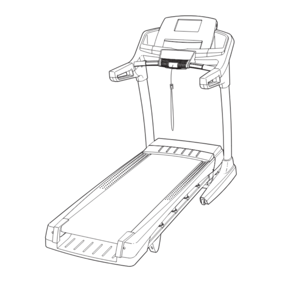
BEFORE YOU BEGIN Thank you for selecting the revolutionary ing this manual, please see the front cover of this man- NORDICTRACK C 900 treadmill. The C 900 treadmill ual. To help us assist you, please note the product ® offers an impressive selection of features designed to model number and serial number before contacting us. -
Page 6: Part Identification Chart
PART IDENTIFICATION CHART Use the drawings below to identify small parts used for assembly. The number in parentheses below each draw- ing is the key number of the part, from the PART LIST near the end of this manual. The number following the key number is the quantity used for assembly. -
Page 7: Assembly
ASSEMBLY • Assembly requires two persons. • To identify small parts, see page 6. • Place all parts in a cleared area and remove the • Assembly requires the following tools: packing materials. Do not dispose of the packing materials until you finish assembly. the included hex keys •... - Page 8 3. Remove the four 5/16" x 1" Screws (5), the four 5/16" Star Washers (11), and the two 5/16" x 1 1/4" Bolts (4) from the Left Handrail (88) and the Right Handrail (87). Save the Screws, Bolts, and Washers. They will be used in as- sembly step 8.
- Page 9 5. Hold the Left Upright (89) against the Base (94). Be careful not to pinch any wires. Insert two 3/8" x 2 3/4" Screws (7) and two 3/8" x 1 1/4" Screws (8) with two 3/8" Star Washers (13) into the Left Upright. Partially tighten the 3/8"...
- Page 10 7. Identify the Left Handrail (88), and hold it near the Left Upright (89). Bracket Tie the wire tie in the Left Handrail (88) securely around the end of the Upright Wire (81). Then, pull the other end of the wire tie until the Upright Wire is routed through the Left Handrail.
- Page 11 9. Set the console assembly face down on a soft surface to avoid scratching the console assem- bly. Remove the four Screws (A). Next, lift off the Crossbar (93) and the Console Frame (104). Discard the four Screws. Console Assembly 10.
- Page 12 11. Attach the Console Frame (104) to the Handrails (87, 88) with four 5/16" x 1 1/4" Bolts (4) and four 5/16" Star Washers (11). Start all four Bolts, and then tighten each of them. 12. With the help of a second person, hold the con- sole assembly near the Left Handrail (88).
- Page 13 13. Set the console assembly on the Left Handrail (88) and the Right Handrail (87). Be careful not to pinch any wires. Insert the excess Upright Console Assembly Wire (not shown) into the Left Handrail. Attach the console assembly with six #8 x 1/2" Screws (1) and two #8 x 3/4"...
- Page 14 15. Raise the Frame (56) to the position shown. Have a second person hold the Frame until step 16 is completed. Orient the Storage Latch (53) so that the large barrel and the latch knob are oriented as shown. Attach the lower end of the Storage Latch (53) to the Base (94) with a 3/8"...
-
Page 15: Operation And Adjustment
OPERATION AND ADJUSTMENT HOW TO PLUG IN THE POWER CORD This product is for use on a nominal 120-volt circuit (see drawing 1). A temporary adapter may be used to DANGER: connect the surge suppressor to a 2-pole receptacle if a properly grounded outlet is not available (see draw- Improper connection ing 2). - Page 16 CONSOLE DIAGRAM FEATURES OF THE CONSOLE You can even listen to your favorite workout music or audio books with the consoleʼs stereo sound system The treadmill console offers an impressive array of while you exercise. features designed to make your workouts more effec- To turn on the power, see page 17.
- Page 17 HOW TO TURN ON THE POWER HOW TO USE THE MANUAL MODE IMPORTANT: If the treadmill has been exposed to 1. Insert the key into the console. cold temperatures, allow it to warm to room tem- perature before you turn on the power. If you do See HOW TO TURN ON THE POWER at the left.
- Page 18 4. Change the incline of the treadmill as desired. The My Trail tab will show a track that represents 1/4 mile (400 m). As you exercise, the white rec- To change the incline of the treadmill, press the tangle will show your progress. The My Trail tab Incline increase or decrease button or one of the will also show the number of laps you complete.
- Page 19 6. Measure your heart rate if desired. 7. Turn on the fan if desired. Before using the The fan features multiple Fan Decrease handgrip heart speed settings. Press rate monitor, re- the fan increase or de- move the sheets crease button to select a of plastic from fan speed or to turn off the metal con-...
- Page 20 HOW TO USE AN ONBOARD WORKOUT progress. The flashing segment of the profile repre- sents the current segment of the workout. The 1. Insert the key into the console. height of the flashing segment indicates the speed or incline setting for the current segment. At the See HOW TO TURN ON THE POWER on page 17.
- Page 21 4. Follow your progress with the displays. HOW TO USE AN IFIT LIVE WORKOUT See step 5 on page 18. If you select an onboard Note: To use an iFit Live workout, you must have an optional iFit Live module. To purchase an iFit Live workout, the display will show the time remaining module at any time, go to www.iFit.com or call the instead of the elapsed time.
- Page 22 7. Measure your heart rate if desired. When you select an iFit Live workout, the display will show the duration of the workout, the distance you will walk or run, and the approximate number of See step 6 on page 19. calories you will burn.
- Page 23 THE INFORMATION MODE function. If the demo mode is turned on, the word ON will appear in the matrix. To turn on or turn off The console features an information mode that keeps the demo mode, press the Enter button. track of treadmill information and allows you to person- 3.
-
Page 24: How To Fold And Move The Treadmill
HOW TO FOLD AND MOVE THE TREADMILL HOW TO FOLD THE TREADMILL HOW TO MOVE THE TREADMILL To avoid damaging the treadmill, adjust the incline Before moving the treadmill, fold it as described at the to the lowest position before you fold the treadmill. left. -
Page 25: Troubleshooting
TROUBLESHOOTING Most treadmill problems can be solved by following c. Remove the key from the console, and then the simple steps below. Find the symptom that reinsert it. applies, and follow the steps listed. If further assis- tance is needed, see the front cover of this manual. d. - Page 26 Locate the Reed Switch (52) and the Magnet (50) b. If the walking belt is overtightened, treadmill perfor- on the left side of the Pulley (49). Turn the Pulley mance may decrease and the walking belt may be- come damaged. Remove the key and UNPLUG until the Magnet is aligned with the Reed Switch.
- Page 27 SYMPTOM: The walking belt is off-center or slips b. If the walking belt slips when walked on, first re- when walked on move the key and UNPLUG THE POWER CORD. Using the hex key, turn both idler roller screws a. If the walking belt is off-center, first remove the clockwise, 1/4 of a turn.
-
Page 28: Exercise Guidelines
EXERCISE GUIDELINES WARNING: Burning Fat—To burn fat effectively, you must exer- cise at a low intensity level for a sustained period of Before beginning this time. During the first few minutes of exercise, your or any exercise program, consult your physi- body uses carbohydrate calories for energy. - Page 29 SUGGESTED STRETCHES The correct form for several basic stretches is shown at the right. Move slowly as you stretch—never bounce. 1. Toe Touch Stretch Stand with your knees bent slightly and slowly bend forward from your hips. Allow your back and shoulders to relax as you reach down toward your toes as far as possible.
-
Page 30: Part List
PART LIST Model No. NTL99010.3 R0611A Key No. Qty. Description Key No. Qty. Description #8 x 1/2" Screw Reed Switch Clip #8 x 3/4" Screw Reed Switch 3/8" x 2" Bolt Storage Latch 5/16" x 1 1/4" Bolt Drive Motor 5/16"... - Page 31 Key No. Qty. Description Key No. Qty. Description Incline Stop Bracket Console Clamp Console Back Left Tray Console Right Tray Console Frame – Userʼs Manual Console Ground Wire Note: Specifications are subject to change without notice. For information about ordering replacement parts, see the back cover of this manual.
-
Page 32: Exploded Drawing
EXPLODED DRAWING A Model No. NTL99010.3 R0611A... - Page 33 EXPLODED DRAWING B Model No. NTL99010.3 R0611A...
- Page 34 EXPLODED DRAWING C Model No. NTL99010.3 R0611A...
- Page 35 EXPLODED DRAWING D Model No. NTL99010.3 R0611A...
-
Page 36: Ordering Replacement Parts
ORDERING REPLACEMENT PARTS To order replacement parts, please see the front cover of this manual. To help us assist you, be prepared to pro- vide the following information when contacting us: • the model number and serial number of the product (see the front cover of this manual) •...
Need help?
Do you have a question about the NTL99010.3 and is the answer not in the manual?
Questions and answers