Table of Contents
Advertisement
www.nordictrack.com
Model No. NTL99113.0
Serial No.
Write the serial number in the space
above for reference.
Serial Number
Decal
ACTIVATE YOUR
WARRANTY
To register your product and
activate your warranty today, go
to www.nordictrackservice.com/
registration.
CUSTOMER CARE
For service at any time, go to
www.nordictrackservice.com.
Or call 1-800-TO-BE-FIT
(1-800-862-3348)
Mon.––Fri. 6 a.m.––6 p.m. MT
Sat. 8 a.m.––12 p.m. MT
Please do not contact the store.
CAUTION
Read all precautions and instruc-
tions in this manual before using
this equipment. Save this manual
for future reference.
USER’'S MANUAL
Advertisement
Table of Contents

Related Manuals for NordicTrack C 970 Pro Treadmill


Summary of Contents for NordicTrack C 970 Pro Treadmill
- Page 1 Model No. NTL99113.0 USER’’S MANUAL Serial No. Write the serial number in the space above for reference. Serial Number Decal ACTIVATE YOUR WARRANTY To register your product and activate your warranty today, go to www.nordictrackservice.com/ registration. CUSTOMER CARE For service at any time, go to www.nordictrackservice.com.
-
Page 2: Table Of Contents
Apply the decal in the location shown. Note: The decals may not be shown at actual size. NORDICTRACK is a registered trademark of ICON IP, Inc. -
Page 3: Important Precautions
18. To purchase a surge suppressor, see your local 4. The treadmill is intended for home use only. NORDICTRACK dealer, call the telephone Do not use the treadmill in any commercial, number on the front cover of this manual, or rental, or institutional setting. - Page 4 20. The heart rate monitor is not a medical 24. Do not change the incline of the treadmill by device. Various factors, including the user’’s placing objects under the treadmill. movement, may affect the accuracy of heart rate readings. The heart rate monitor is 25.
- Page 6 STANDARD SERVICE PLANS...
-
Page 7: Before You Begin
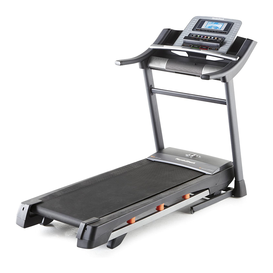
Thank you for selecting the revolutionary reading this manual, please see the front cover of this NORDICTRACK C 970 PRO treadmill. The C 970 manual. To help us assist you, please note the product ® PRO treadmill offers an impressive selection of fea- model number and serial number before contacting us. -
Page 8: Part Identification Chart
PART IDENTIFICATION CHART Use the drawings below to identify small parts used for assembly. The number in parentheses below each draw- ing is the key number of the part, from the PART LIST near the end of this manual. The number following the key number is the quantity used for assembly. -
Page 9: Assembly
ASSEMBLY •• Assembly requires two persons. •• To identify small parts, see page 8. •• Place all parts in a cleared area and remove the •• Assembly requires the following tools: packing materials. Do not dispose of the packing materials until you nish all assembly steps. the included hex key ••... - Page 10 2. Make sure that the power cord is unplugged. Wire Press the two Base Caps (74) into the Base (94) if they are not already in the Base. Identify the Right Upright (90). Remove and discard the indicated screw (A). Have a second person hold the Right Upright near the Base (94).
- Page 11 4. Insert a Wheel Spacer (63) into a Front Wheel (62). Hold the Front Wheel inside the bottom of the Right Upright (90), and insert a 3/8" x 4" Screw (7) with a 3/8" Star Washer (13) into the Right Upright and the Front Wheel. Repeat this step on the left side of the treadmill.
- Page 12 6. Remove and save the four indicated 5/16" x 3/4" Screws (4); the Screws will be used in a later step. Identify the Left and Right Base Covers (82, 83). Slide the Left Base Cover onto the Left Upright (89), and slide the Right Base Cover onto the Right Upright (90).
- Page 13 8. Insert the wires into the Right Upright (90) as you set the console assembly on the Left and Right Uprights (89, 90). Be careful not to pinch Console the Upright Wire (81). Assembly Attach the console assembly with four 5/16" x 1 1/2"...
- Page 14 10. Carefully slide the Upright Crossbar (41) between the Uprights (89, 90). Attach the Upright Crossbar with the four 5/16" x 3/4" Screws (4) that you removed in step 6 and four 5/16" Star Washers (11). Start all four Screws, and then tighten them.
- Page 15 12. Note: If assembled on a smooth surface, the treadmill may roll forward during this step. Raise the Frame (56) to the upright position. Brackets Have a second person hold the Frame until step 14 is completed. Remove the two 5/16" x 3/4" Screws (4) from the Latch Crossbar (38).
- Page 16 14. Align the upper end of the Storage Latch (53) with the bracket on the Latch Crossbar (38). Insert a 5/16" x 2 1/4" Bolt (3) through the bracket. This should push a spacer (E) out of the other end. Discard the spacer. Attach the Storage Latch (53) with the 5/16"...
-
Page 17: The Chest Heart Rate Monitor
THE CHEST HEART RATE MONITOR HOW TO PUT ON THE HEART RATE MONITOR •• Do not expose the heart rate monitor to direct sun- light for extended periods of time; do not expose it to The heart rate temperatures above 122° F (50° C) or below 14° F monitor consists of (-10°... -
Page 18: Operation And Adjustment
OPERATION AND ADJUSTMENT HOW TO CONNECT THE POWER CORD nominal 120-volt circuit capable of carrying 15 or more amps. To avoid overloading the circuit, do Use a Surge Suppressor not plug other electrical devices, except for low- power devices such as cell phone chargers, into Your treadmill, like other electronic equipment, can be the surge suppressor or into an outlet on the same damaged by sudden voltage changes in your home’’s... - Page 19 CONSOLE DIAGRAM FEATURES OF THE CONSOLE You can even listen to your favorite workout music or audio books with the console’’s sound system while you The treadmill console offers an impressive array of exercise. features designed to make your workouts more effec- tive and enjoyable.
- Page 20 HOW TO TURN ON THE POWER HOW TO USE THE MANUAL MODE IMPORTANT: If the treadmill has been exposed to 1. Insert the key into the console. cold temperatures, allow it to warm to room tem- perature before you turn on the power. If you do See HOW TO TURN ON THE POWER at the left.
- Page 21 4. Change the incline of the treadmill as desired. The My Trail tab will show a track that represents 1/4 mile (400 m). As you exercise, the ashing rect- To change the incline of the treadmill, press the angle will show your progress. The My Trail tab will Incline increase or decrease button or one of the also show the number of laps you complete.
- Page 22 6. Measure your heart rate if desired. 7. Turn on the fan if desired. Note: If you use the handgrip heart rate moni- The fan features multiple speed settings and an tor and the chest heart rate monitor at the same auto mode.
- Page 23 HOW TO USE AN ONBOARD WORKOUT programmed for the next segment, the speed and/ or incline setting will ash in the display and the 1. Insert the key into the console. treadmill will automatically adjust to the new speed and/or incline setting.
- Page 24 HOW TO USE A SET-A-GOAL WORKOUT HOW TO USE AN IFIT WORKOUT 1. Insert the key into the console. Note: To use an iFit workout, you must have an optional iFit module. To purchase an iFit module at See HOW TO TURN ON THE POWER on page 20. any time, go to www.iFit.com or call the telephone number on the front cover of this manual.
- Page 25 For more information about the iFit workouts, During a competition workout, the Competition tab please see www.iFit.com. will show your progress in the race. As you race, the top line in the matrix will show how much of the When you select an iFit workout, the display will race you have completed.
- Page 26 THE SETTINGS MODE displays will remain lit, although the buttons will not function. If the demo mode is turned on, the word The console features a settings mode that keeps track ON will appear in the matrix. To turn on or turn off of treadmill information and allows you to personalize the demo mode, press the Enter button.
- Page 27 HOW TO ADJUST THE CUSHIONING SYSTEM The treadmill features a cushioning system that reduces the impact as you walk or run on the treadmill. Remove the key from the console and unplug the power cord. To adjust the cushions, you may need to place the treadmill in the storage position (see HOW TO FOLD THE TREADMILL on page 28).
-
Page 28: How To Fold And Move The Treadmill
HOW TO FOLD AND MOVE THE TREADMILL HOW TO FOLD THE TREADMILL HOW TO MOVE THE TREADMILL To avoid damaging the treadmill, adjust the incline Before moving the treadmill, fold it as described at the to zero before you fold the treadmill. Then, remove left. -
Page 29: Troubleshooting
TROUBLESHOOTING Most treadmill problems can be solved by following c. Remove the key from the console, and then the simple steps below. Find the symptom that reinsert it. applies, and follow the steps listed. If further assis- tance is needed, see the front cover of this manual. d. - Page 30 Locate the Reed Switch (52) and the Magnet (50) b. If the walking belt is overtightened, treadmill per- on the left side of the Pulley (49). Turn the Pulley formance may decrease and the walking belt may until the Magnet is aligned with the Reed Switch. become damaged.
- Page 31 SYMPTOM: The walking belt is off-center or slips b. If the walking belt slips when walked on, rst when walked on remove the key and UNPLUG THE POWER CORD. Using the hex key, turn both idler roller a. If the walking belt is off-center, rst remove the screws clockwise, 1/4 of a turn.
-
Page 32: Exercise Guidelines
EXERCISE GUIDELINES Burning Fat——To burn fat effectively, you must exer- WARNING: cise at a low intensity level for a sustained period of Before beginning this time. During the first few minutes of exercise, your or any exercise program, consult your physi- body uses carbohydrate calories for energy. -
Page 33: Suggested Stretches
SUGGESTED STRETCHES The correct form for several basic stretches is shown at the right. Move slowly as you stretch ——never bounce. 1. Toe Touch Stretch Stand with your knees bent slightly and slowly bend forward from your hips. Allow your back and shoulders to relax as you reach down toward your toes as far as possible. -
Page 34: Part List
PART LIST Model No. NTL99113.0 R1113A Key No. Qty. Description Key No. Qty. Description #8 x 1/2" Screw Reed Switch Clip #8 x 3/4" Screw Reed Switch 5/16" x 2 1/4" Bolt Storage Latch 5/16" x 3/4" Screw Drive Motor #8 x 5/8"... - Page 35 Key No. Qty. Description Key No. Qty. Description Hood Post Heart Rate Monitor #8 x 3/8" Screw Incline Motor Spacer #8 x 3/4" Machine Screw Handrail Spacer Console Base Back Pulse Sensor Electronics Bracket Right Foot Pad Base Pad Left Foot Pad ––...
-
Page 36: Exploded Drawing
EXPLODED DRAWING A Model No. NTL99113.0 R1113A... - Page 37 EXPLODED DRAWING B Model No. NTL99113.0 R1113A...
- Page 38 EXPLODED DRAWING C Model No. NTL99113.0 R1113A...
- Page 39 EXPLODED DRAWING D Model No. NTL99113.0 R1113A...
-
Page 40: Ordering Replacement Parts
ORDERING REPLACEMENT PARTS To order replacement parts, please see the front cover of this manual. To help us assist you, be prepared to provide the following information when contacting us: •• the model number and serial number of the product (see the front cover of this manual) ••...
Need help?
Do you have a question about the C 970 Pro Treadmill and is the answer not in the manual?
Questions and answers
How do I disassemble and disconnect the electronics to separate the machine into two or three pieces so I and a second person can take each piece up a 3 foot wide staircase with a sharp turn at the top?