
Subscribe to Our Youtube Channel
Related Manuals for urmet domus Sinthesi S2 1083


Summary of Contents for urmet domus Sinthesi S2 1083
- Page 1 Mod. 1083 DS 1083-035D LBT 8757 MODULO DI CHIAMATA DIGITALE 2VOICE 2VOICE DIGITAL CALL MODULE Sch./Ref. 1083/19...
-
Page 2: Installazione
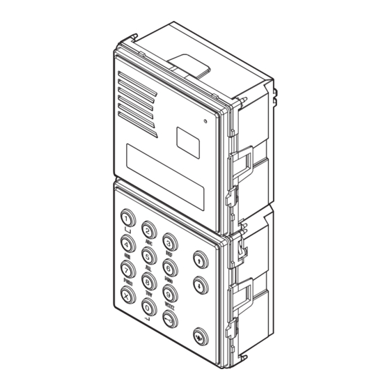
ITALIANO Le caratteristiche del modulo di chiamata 1083/19 sono le seguenti: • Può chiamare tutti i potenziali utenti dell’impianto (128 utenti per 32 colonne) tramite digitazione del codice fisico (2 cifre per il numero di colonna e 3 cifre per il numero di appartamento). • Display di 2 righe da 16 caratteri con visualizzazione rubrica degli utenti. • Tastiera alfanumerica. • Gestisce fino a 4200 nominativi in rubrica; a ogni nominativo può essere associato un codice apriporta di 4 cifre. • Possibilità di associare ai nominativi codici logici di chiamata di 4 cifre. • Possibilità di gestire 100 codici apriporta scorrelati dai nominativi. • Ricerca nominativo tramite scorrimento e tramite ricerca sulla lettera iniziale. • Gestione di elettroserratura pedonale con scarica capacitiva e corrente di mantenimento e anche con uscita a relè in scambio. - Page 3 • Posizionare la cornice sul telaio • Serrare le viti B sulle viti A DS1083-035D...
- Page 4 DESCRIZIONE MORSETTI / PREDISPOSIZIONI V5 Riferimento per segnale telecamera di controllo / commutatore video V3 Segnale telecamera di controllo / commutatore video Azionamento elettroserratura pedonale Positivo azionamento elettroserratura pedonale con scarica capacitiva Negativo azionamento elettroserratura pedonale con scarica capacitiva Non usare LINE Linea Bus entrante T- Riferimento per commutatore video Comando per commutatore video CT Riferimento per PA e SP Sensore porta aperta Pulsante androne SE2 Azionamento elettroserratura passo carraio (contatto NA) Non usare...
- Page 5 COLLEGAMENTO MODULO TELECAMERA Per il collegamento del modulo telecamera Sch. 1748/40 (a colori), sul retro del modulo di chiamata è previsto un connettore per il cavetto fornito a corredo: ROSSO - Positivo di alimentazione (+TC) NERO - Negativo di alimentazione (R1) BIANCO - Cavo coassiale per segnale video (V3, V5) Led della telecamera spenti Sch. 1083/19 Led della telecamera accesi (default)
- Page 6 PROGRAMMAZIONE DELLA CONFIGURAZIONE Il menu di configurazione è così composto: Uscita dalla CONFIGURAZIONE programmazione TIPO MODULO <PRI> <SEC> Solo se secondario ID MODULO SECONDARIO <0> <1> TIPO CODICE <FISI> <LOGIC> TIPO DISPOSITIVO <AUDIO> <VIDEO> TEMPO OCCUPATO INTERROMPIBILE <SI> <NO> In caso di inserimento valori T APRIPORTA 1 non validi, compare la videata CODICE NON AMMESSO...
-
Page 7: Parametri Di Configurazione
PARAMETRI DI CONFIGURAZIONE Per accedere al menù di configurazione, digitare il codice 99999 seguito dalla password (default 1000) e dal tasto . Poi premere il tasto e premere Con il tasto si conferma la scelta; con il tasto X, si cancella la scelta. Premendo il tasto X per 3s, si torna all’inizio del menù dal quale è possibile uscire ripremendo il tasto X. • Tipo modulo Il modulo può essere configurato come principale o come secondario. Dal modulo principale è possibile chiamare tutti gli utenti dell’impianto, dal modulo secondario è possibile chiamare solo gli utenti della colonna di appartenenza. L’utente che riceve la chiamata è in grado di distinguerne la provenienza dalla temporizzazione con cui viene emesso lo squillo. - Page 8 • T Apriporta 1 È il tempo di mantenimento dell’elettroserratura pedonale (morsetti SE+/SE-) e di attivazione dei morsetti C/NC/NO. Il numero digitabile (espresso in secondi) è compreso tra 1 e 90. • Tipo apriporta 1 L’elettroserratura può essere gestita in modalità ‘sotto segreto’ o ‘libero’. Il comportamento del posto esterno è il seguente nei due casi: – ‘Sotto segreto’: la pressione del pulsante apriporta di un posto interno può attivare l’elettroserratura della postazione di chiamata solo se ha ricevuto una chiamata o è in conversazione fonica con essa o anche se, in seguito ad autoinserzione, è comunque in connessione video con essa.
- Page 9 CONFIGURAZIONE DEFAULT DEI MODULI DI CHIAMATA Lingua: italiano Tipo modulo: principale ID modulo: Tipo codice: codice fisico Tipo dispositivo: video Tempo occupato: Interruzione: non abilitata Tempo serratura pedonale: Tipo apriporta pedonale: segreto Tempo apriporta carraio: Tipo apriporta carraio: segreto Password: 1000 Numero telecamere di controllo: 0 Tono tasti: Funzione postino: Per riportare i valori di default alimentare il dispositivo tenendo premuti i tasti X, 8 e 6.
- Page 10 Premendo il tasto X si cancella il codice. Premendo il tasto X in assenza di caratteri inseriti, si torna al passo precedente. In caso di inserimento di un codice non valido, compare un messaggio di errore ed è necessario reinserire il dato. CODICE LOGICO: In caso di impostazione del dispositivo con tipo codice = codici fisici, questa videata non compare. Inserire il codice logico di chiamata dell’appartamento che deve essere un numero da 1 a 4 cifre compreso tra 1 e 9999. Premendo si passa al codice apriporta. Premendo il tasto X si cancella il codice. Premendo il tasto X in assenza di caratteri inseriti, si torna al passo precedente. In caso di inserimento di un codice non valido, compare un messaggio di errore ed è necessario reinserire il dato. Il codice logico deve essere univoco nella rubrica programmata. CODICE APRIPORTA: Se non si vuole associare un codice apriporta all’utente inserito, premere il tasto Se si vuole associare un codice apriporta all’utente inserito, inserire il codice apriporta che deve essere un numero di 4 cifre compreso tra 0001 e 4999. Tale codice aprirà il cancello pedonale; se, invece, si vuole aprire il passo carraio, inserire un codice apriporta compreso tra 5000 e 9999. Dopo l’inserimento, premere il tasto Premendo il tasto X si cancella il codice. Premendo il tasto X in assenza di caratteri inseriti, si torna al passo precedente.
- Page 11 PROGRAMMAZIONE DEI CODICI APRIPORTA In questo menù è possibile gestire i codici apriporta non legati ai nominativi della rubrica. Il menù è così composto: INSERISCI MODIFICA CANCELLA CANCELLA TUTTO Con i tasti freccia è possibile scorrere il menù di programmazione codici apriporta; con il tasto X, si esce dalla programmazione. • Inserisci CODICE APRIPORTA: Inserire il codice apriporta che deve essere un numero di 4 cifre compreso tra 0001 e 9999. Tale codice aprirà il cancello pedonale se è compreso tra 1 e 4999; aprirà il passo carraio se è compreso tra 5000 e 9999. Dopo l’inserimento, premere il tasto Premendo il tasto X si cancella il codice. Premendo il tasto X in assenza di caratteri inseriti, si torna al passo precedente. In caso di inserimento di un codice non valido o già presente, compare un messaggio di errore ed è necessario reinserire il dato.
- Page 12 REGOLAZIONE LIVELLI FONICI I livelli fonici sono tarati di fabbrica in modo da non dover essere variati nella maggioranza delle installazioni. Qualora fosse necessario modificarli, agire con un cacciavite sulle apposite regolazioni. CHIAMATE AGLI UTENTI Il modulo di chiamata visualizza a riposo: SELEZIONARE NOME ↑↓ E PREMERE Se non sono stati inseriti nomi nella rubrica, invece, compare la scritta DIGITARE CODICE PREMERE CHIAMATA TRAMITE DIGITAZIONE CODICE FISICO Se il modulo di chiamata è configurato a codici fisici, inserire il codice di 5 cifre così composto: ccnnn, dove cc indica la colonna (da 00 a 31) e nnn indica il numero dell’appartamento (da 000 a 127). In impianti senza interfaccia di colonna Sch. 1083/50 il codice di colonna è 00. Sul display compaiono le cifre digitate: CODICE: 01003 Con il tasto X, è possibile cancellare la digitazione; con il tasto , se il sistema è libero e il codice è valido, viene effettuata la chiamata e il display visualizza per tutto il tempo di attesa sgancio (massimo 60s): IN CHIAMATA Se, invece, il codice non è valido, compare la videata:...
- Page 13 LINEA OCCUPATA ATTENDERE Quando il sistema torna libero, è possibile richiamare. E’ possibile digitare un codice fisico che inizia con degli zeri omettendoli (ad esempio il codice fisico 1001 chiamerà la colonna 01 utente 001). CHIAMATA TRAMITE DIGITAZIONE CODICE LOGICO Se il modulo di chiamata è configurato a codici logici, inserire il codice di massimo 4 cifre. Sul display compaiono le cifre digitate: CODICE: 1002 Con il tasto X, è possibile cancellare la digitazione; con il tasto , se il sistema è libero e il codice è valido, viene effettuata la chiamata e il display visualizza per tutto il tempo di attesa sgancio (massimo 60s): IN CHIAMATA Se, invece, il codice non è valido, compare la videata: CODICE ERRATO e, poi, il display torna a riposo; Se, invece, il codice è valido ma il sistema è occupato, compare la videata: LINEA OCCUPATA ATTENDERE Quando il sistema torna libero, è possibile richiamare. CHIAMATA TRAMITE SELEZIONE NOME DALLA RUBRICA Premere i tasti freccia per scorrere l’elenco dei nomi in ordine alfabetico.
- Page 14 nominativo che comincia con la lettera digitata; ricercare il nome desiderato con i tasti freccia. • Per esempio, per cercare il nome “ROSSI”, dalla visualizzazione precedente, premere il tasto 7 tre volte per posizionare la rubrica sul primo nome che inizia con la “R”; in mancanza di nomi che iniziano con la lettera “R”, il display si posiziona sul primo nominativo seguente in ordine alfabetico. Con i tasti freccia, è possibile navigare la rubrica partendo dal nome visualizzato. CHIAMATA A CENTRALINO Se sull’impianto è presente un centralino di portineria in stato di funzionamento “giorno”, tutte le chiamate effettuate da moduli di chiamata principali vengono da questo intercettate e gestite. E’ anche possibile chiamare il centralino in stato “giorno” digitando direttamente il tasto senza effettuare alcuna selezione oppure premendo contemporaneamente più pulsanti. Se il sistema è libero, viene effettuata la chiamata e il display visualizza per tutto il tempo di attesa sgancio (massimo 60s): IN CHIAMATA Se il sistema è occupato, compare la videata: LINEA OCCUPATA...
- Page 15 Continuando a tenere premuto il tasto 0 per 2s, il modulo di chiamata passa in modalità codici speciali e compare la scritta: CODICE SPECIALE: Inserire il codice di 3 cifre (da 1 a 255) programmato nella decodifica speciale da comandare. Il display visualizza tale codice con degli *: CODICE SPECIALE: 0*** Con il tasto X è possibile annullare la digitazione; al termine della digitazione, premere il tasto per inviare il codice. Il display torna a riposo. GESTIONE DELLE SERRATURE Il modulo di chiamata è...
-
Page 16: Caratteristiche Tecniche
FUNZIONE “POSTINO” Se sul modulo di chiamata sono state programmate delle fasce orarie e la funzione è attiva, nei giorni e ore stabilite, è possibile aprire direttamente la porta pedonale con la sola pressione del tasto Dopo la pressione di questo tasto, è comunque possibile inserire un eventuale codice apriporta per l’apertura del passo carraio. PROGRAMMAZIONE VIA BLUETOOTH Il modulo di chiamata è dotato di ricetrasmettitore Bluetooth per la programmazione facilitata di configurazione, nomi e codici apriporta. Entrare in programmazione digitando la password, attivare il software 2Voice_Mobile (scaricabile dal sito Urmet) precedentemente installato sul PDA o sul telefono ed eseguire, dal telefono, la connessione tra il software del telefono e il modulo di chiamata. -
Page 17: Panel Installation
ENGLISH The Ref. 1083/19 call module offers the following functions: • Possibility of calling all potential system users (128 users for 32 risers) by entering the physical code (2 digits for the riser number and 3 digits for the apartment number). • Two 16-character row LCD with display of user repertory. • Alphanumeric keypad • 4200-name repertory; a 4-digit door-opener code can be assigned to each name. • Possibility of associating 4-digit logical call codes to the names. • 100 door-opener codes not associated with names. • Name selection using arrow keys and search by initial letter. • Management of main entrance electric lock with capacitance discharge and holding current and also with changeover relay output. • Output contact for control of vehicle entrance electric lock. • Door-opener pulse (unrestricted or protected by privacy feature). • Postman function: direct opening of main entrance with key on days and at times programmed. • Direct call to switchboard if two buttons are pressed at the same time. • Management of main entrance Hall button. • Management of main entrance door sensor. • Management of video input for surveillance camera and T signal management for Ref. 1038/69 video switch. - Page 18 • Position the panel on the frame. • Fasten the screws B on screws A. DS1083-035D...
- Page 19 DESCRIPTION OF TERMINALS / SETTINGS V5 Reference for control camera signal / video switch V3 Control camera signal / video switch Activation main entrance electric lock SE+ Positive activation main entrance electric lock with capacitance discharge SE- Negative activation main entrance electric lock with capacitance discharge Do not use LINE Bus line in T- Reference for video switch T+ Command for video switch CT Reference for PA and SP Open door detector PA Hall button SE2 Driveway electric lock activation (NO contact) Do not use ILA Output of device for deaf people Ref. 1148/48 Do not modify the position...
- Page 20 CAMERA MODULE CONNECTION A 3-wire connector is provided for connecting the Ref. 1748/40 (colour) camera module to the back of the calling module: RED - Power positive (+TC) BLACK - Power negative (R1) WHITE - Video signal coax (V3, V5) Camera leds off Ref. 1083/19 Camera leds on (default) Ref. 1748/40 V3 - V5 System with coaxial cable PROGRAMMING Enter the code 99999 to access the configuration and programming menu; the display shows: PASSWORD Enter the password (default 1000) and press to access the following programming menu: LANGUAGE Select the operating language and confirm with CONFIGURATION See “configuration programming” on page 21 NAMES See “name programming” on page 24 DOOR OPENER See “programming of door-opener codes” on page 25 Use the arrow keys to scroll the programming menu. Press...
-
Page 21: Configuration Programming
CONFIGURATION PROGRAMMING The configuration menu is as follows: CONFIGURATION Exit programming MODULE TYPE <PRI> <SEC> Only if secondary MODULE ID SECONDARY <0> <1> CODE TYPE <PHYS> <LOGIC> DEVICE TYPE <AUDIO> <VIDEO> BUSY TIME STOPABLE <YES> <NO> If the value entered is not DOOR LOCK T1 correct, the display shows CODE NOT ALLOWED... -
Page 22: Configuration Parameters
CONFIGURATION PARAMETERS To access the configuration menu, enter the code 99999 followed by the password (default 1000) and the key. Then, press the key and press Press to confirm selection; press X to cancel selection. Pressing X for 3s returns to the start of the menu; to quit, press X again. • Module type The calling module may be a main or secondary device. All systems users can be called from the main device; only users of the related riser column can be called from the secondary device. The user who receives the call is able to distinguish the origin of the call according to ring duration. - Page 23 Electric lock control may be “protected by privacy feature” or “unrestricted”. The door unit behaves as follows in the two cases: – ‘Private’: pressing the door-opener button of an apartment station, the electric lock of the call station is released only if a call has been received or a voice conversation is in progress with this or if, following auto power-on, it is in video connection with this. – ‘Unrestricted’: pressing the door-opener button of an apartment station, the electric lock of the door unit is released only if this has been configured as main, or the user belongs to the riser column of the same secondary door unit. This riser column is defined by the ID of the secondary door unit. This function is normally used on secondary stations. • Door lock T2 Activation time of the vehicle entrance electric lock (SE2 terminals). Enter a number (in seconds) from 1 to • Door opener 2 The electric lock may be controlled in “private” or “unrestricted” mode. The door unit behaves as follows in the two cases: – ‘Private’: pressing the door-opener button of an apartment station, the electric lock of the call station is released only if a call has been received or a voice conversation is in progress with this or if, following auto power-on, it is in video connection with this. – ‘Free’: pressing the door-opener button of an apartment station, the electric lock of the door unit is released only if the door unit is configured as main, or the user belongs to the riser column of the same secondary door unit. This riser column is defined by the ID of the secondary door unit. This function is normally used on secondary stations. • Password Password for accessing configuration and programming of call module data. Set a value from 1000 to 9999 (default 1000). • Control cameras Number of surveillance cameras connected to terminals V3/V5 (if more than one, via the 1038/69 video switch).
-
Page 24: Name Programming
CALL MODULE DEFAULT CONFIGURATION Language: Italian Module type: main Module ID: Code type: physical code Device type: video Busy time: Interruption: not enabled Main entrance lock time: 1s Type of main entrance door-opener: private Vehicle entrance door-opener time: Type of vehicle entrance door opener: private Password: 1000 Number of surveillance cameras: Key click: Postman function: To restore the default values, power the device holding down the X, 8 and 6 keys. NAME PROGRAMMING The name programming menu is as follows: ENTER... -
Page 25: Delete All
If the code entered is not valid, an error message is displayed and the data must be re-entered. LOGICAL CODE: If the device is set with code type = physical codes, this screen page is not displayed. Enter the logical call code of the apartment which must be a a number of 1 to 4 digits from 1 to 9999. Press to move to the door-opener code. Press X to cancel the code. Pressing X without inserting characters returns to the previous step. If the code entered is not valid, an error message is displayed and the data must be re-entered. The logical code must be univocal in the repertory programmed. DOOR OPENER CODE If a door-opener code is not to be assigned to the user inserted, press If a door-opener code to be assigned to the user inserted, enter the door-opener code which must be a 4- digit number from 0001 to 4999. This code will open the main entrance; to open the vehicle entrance, enter a door-opener code from 5000 to 9999. After insertion, press Press X to cancel the code. Pressing X without inserting characters returns to the previous step. If the code entered is not valid or already exists, an error message is displayed and the data must be re- entered. After this step, the name is inserted in the repertory and a new name can be inserted. • Modify From this menu, the repertory can be scrolled using the arrow keys; press to modify the data following the same screen pages as for insertion. • Delete From this menu, the repertory can be scrolled using the arrow keys; pressing , confirmation of deletion is requested. • Delete all From this menu, the entire names repertory can be deleted; pressing , confirmation of deletion is requested. - Page 26 Enter the door-opener code which must be a 4-digit number from 0001 to 9999. A code between 1 and 4999 will open the main entrance; a code between 5000 and 9999 will open the vehicle entrance. After insertion, press Press X to cancel the code. Pressing X without inserting characters returns to the previous step. If the code entered is not valid or already exists, an error message is displayed and the data must be re- entered. • Modify From this menu, the list of the door-opener codes can be scrolled with the arrow keys; press to modify the code selected. • Delete From this menu, the list of the door-opener codes can be scrolled with the arrow keys; pressing confirmation of deletion is requested.
- Page 27 CALLS TO USERS In stand-by mode, the call module displays: SELECT NAME ↑↓ AND PRESS If no names have been inserted in the repertory, the display shows TYPE CODE PRESS CALL BY ENTERING PHYSICAL CODE If the call module is configured with physical codes, enter the 5-digit code as follows: ccnnn, where cc indicates the riser column (from 00 to 31) and nnn indicates the number of the apartment (from 000 to 127). In systems without Ref.1083/50 riser column interface, the riser column code is 00. The digits entered are displayed: CODE: 01003 Use X to delete the character if you make a mistake; with...
- Page 28 If the code is valid but the system is busy, the display shows: LINE BUSY WAIT When the system is free again, the call can be repeated. CALL BY SELECTING NAME FROM REPERTORY Press the arrow keys to scroll the list of names in alphabetical order. The names are shown on the display: ROSSI MARIO Pressing X, stand-by status is restored; with , if the system is free, the call is made and for the entire pick-up wait time (max. 60s) the display shows: CALLING If the system is busy, the display shows: LINE BUSY WAIT When the system is free again, the call can be repeated. If the repertory contains a high number of names, to make a faster search, proceed as follows. • Press an arrow key once to display the repertory. • A name is displayed: ABATE MARIO • Use the keypad to select the initial letter of the name to be found; the first name that starts with the letter indicated is displayed; use the arrow keys to search for the name required. • For example, to find the name “ROSSI”, from the previous display, press the 7 key three times to position the repertory on the first name starting with “R”; if there are no names starting with “R”, the first name in alphabetical order is displayed. Use the arrow keys to navigate the repertory starting from the name displayed.
-
Page 29: Lock Management
COMMUNICATION AND DOOR OPENING If a call is made, when the user lifts the hand-set, the module establishes a conversation and for the entire communication time (max. 10 minutes) the display shows: SPEAK PLEASE If the user presses the button to open the main or vehicle entrance, the module activates the corresponding output with temporary display of: COME IN PLEASE When the user called hangs up, the communication is closed and the module returns to stand-by status. If the call is intercepted by the switchboard and this puts the call module on hold in order to call an apartment station, the display shows: WAIT PLEASE When communication between the module and the switchboard or directly with the apartment station called by the switchboard is restored, the display shows: SPEAK PLEASE TRANSMISSION OF SPECIAL CODES If the system comprises special decoders, the call module can send commands to activate load driving outputs (lights, gates, etc.) When the call module is on stand-by, pressing the 0 key, the display shows CODE: Continuing to press the 0 key for 2s, the call module switches to special code mode and the display shows: SPECIAL CODE: Enter the 3-digit code (from 1 to 255) programmed in the special decoder to be activated. The display... -
Page 30: Simplified Eu Declaration Of Conformity
ENTRY OF DOOR-OPENER CODES If door-opener codes (unrestricted or associated with names in the repertory) have been programmed on the call module, the door (pedestrian or vehicle) can be opened entering this code. The main entrance lock is activated for codes from 0001 to 4999; the vehicle entrance lock is activated for codes from 5000 to 5999. When the call module is on stand-by, pressing the key , the display shows CODICE APERTURA PORTA: Enter the 4-digit door-opener code programmed. The display shows this code with *: DOOR LOCK RELEASE CODE: **** Press X to delete the data if you make a mistake; after entry, press The display returns to stand-by status. If the code is amongst those programmed, the lock is activated and the display shows: COME IN PLEASE... -
Page 31: Technical Specifications
TECHNICAL SPECIFICATIONS 36 – 48 V Power voltage (LINE): 36 – 48 V Power voltage (+ -): Max 85 mA Stand-by consumption: 220 mA Max. consumption (Video call) capacitance discharge 22-24 V Lock output SE+ SE-: + holding current max 200 mAdc Max 24 V 5A Lock relay C/NC/NO: Max 24 V 300 mA Lock relay SE2: - 10 °C + 50 °C... - Page 32 ITALIANO DIRETTIVA 2012/19/UE DEL PARLAMENTO EUROPEO E DEL CONSIGLIO del 4 luglio 2012 sui rifiuti di apparecchiature elettriche ed elettroniche (RAEE) Il simbolo del cassonetto barrato riportato sull’apparecchiatura o sulla sua confezione indica che il prodotto alla fine della propria vita utile deve essere raccolto separatamente dagli altri rifiuti. L’utente dovrà, pertanto, conferire l’apparecchiatura giunta a fine vita agli idonei centri comunali di raccolta differenziata dei rifiuti elettrotecnici ed elettronici. In alternativa alla gestione autonoma è possibile consegnare l’apparecchiatura che si desidera smaltire al rivenditore, al momento dell’acquisto di una nuova apparecchiatura di tipo equivalente.
Need help?
Do you have a question about the Sinthesi S2 1083 and is the answer not in the manual?
Questions and answers