Advertisement
Quick Links
- Brochure
tekmarNet
®
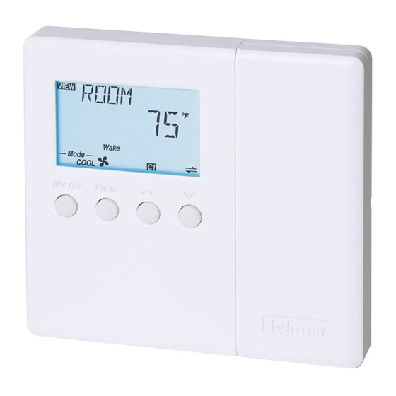
4 Thermostat 545
1
2
Information
Application
Brochure
Choose controls
Design your
to match
mechanical
application
applications
Introduction
®
The tekmarNet
4 thermostat 545 operates two stages of heating equipment, one stage of cooling equipment, and one fan.
The fan operation includes logic to operate ventilation. The 545 can operate as a stand alone device, or communicate with
a group of tekmarNet
®
4 thermostats.
Features
•
• tN4 Compatible
• • Automatic Heat / Cool Switchover
• • 2 Auxiliary Temperature Sensor Inputs
• • Pulse Width Modulation
3
Rough In
Brochure
Wiring
Rough-in
wiring
instructions
4
Wiring
Brochure
Wiring and
installation of
specific control
• • Programmable Setback and Setup Scheduling
• • Scenes
• • Cooling Group
• • Radiant Base Load
Y1 Rc G1 G1
Com
S2
S1
tN4
C
R
Rh1
W1
Rh2 W2
1 of 40
5
6
Data
Brochure
Control settings
Record settings &
and sequence of
wiring details for
operation
future reference
© 2005
D 545
06/05
Job
Record
D 545 - 06/05
Advertisement

Related Manuals for Tekmar 545 tekmarNet 4


Summary of Contents for Tekmar 545 tekmarNet 4
- Page 1 - Brochure D 545 tekmarNet ® 4 Thermostat 545 06/05 Information Application Rough In Wiring Data Brochure Brochure Wiring Brochure Brochure Record Wiring and Control settings Choose controls Design your Rough-in Record settings & installation of and sequence of to match mechanical wiring wiring details for...
- Page 2 Table of Contents Table of Contents ............2 Heating Terminal Units .........26 Display and DIP Switches ..........2 Heating Operation ..........27 Dip Switches ............2 Cooling Operation ..........29 Access Levels ............3 Cool Groups ............29 Display and Symbols Description ......3 Fan Operation ............30 User Interface ............4 Filter Change ............
- Page 3 Access Levels The Access Level restricts the number of Menus, Items For more information, see the Misc (Miscellaneous) Menu and Adjustments that can be accessed by the user. The section. Access Level setting is found in the Miscellaneous (MISC) In the following menu tables, the access level the item is menu.
- Page 4 User Interface Use the User Interface available on the Liquid Crystal Display Adjusting a Setting (LCD) to setup and monitor the operation of the thermostat. To adjust a setting: Use the four push buttons below the LCD (Menu, Item, Up, Down) to select settings.
- Page 5 Display Menus View Menu (1 of 2) The View menu items display the current operating temperatures and status information of the system. Item Field Range Access Description COOL AVERAGE SECTION H Average room temperature of the cool group master -58 to 212°F and members.
- Page 6 View Menu (2 of 2) Item Field Range Access Description DUCT SENSOR SECTION A INST Current temperature at the duct sensor. -58 to 212°F (-50.0 to 100.0°C) Note: This item is only available when Sensor 2 is set to Duct. SUPPLY TEMPERATURE OF TN4 BUS SECTION F Actual water temperature of the tN4 bus for the first...
- Page 7 Adjust Menu (2 of 7) Item Field Range Access Description 50 to 100°F (10.0 to 38.0°C) SET COOL SECTION C Select the cooling room temperature for each event. USER Wake Default = 78°F (25.5°C) Note: At the Limited Access Level, you can only INST UnOccupied Default = 85°F (29.5°C)
- Page 8 Adjust Menu (3 of 7) Item Field Range Access Description HEAT CYCLES PER HOUR SECTION D Select the number of heating cycles per hour. SYNC SYNC, AUTO results in 5 CPH. All tN4 thermostats that are connected 2 to 12 and have the SYNC setting selected synchronize their cycle to the same starting time.
- Page 9 Adjust Menu (4 of 7) Item Field Range Access Description HEAT 2 DELAY SECTION F Select whether the system, primary, or mixing pump on a tN4 System Control is delayed to allow a second stage heat thermal motor zone valve to open. Select OFF, ON INST On for thermal motor, select Off for zone pump or...
- Page 10 Adjust Menu (5 of 7) Item Field Range Access Description PRIORITY HEATING OR COOLING SECTION G Select whether heating has priority or cooling has HEAT, COOL priority. Default = COOL Note: This item is only available when the Cool Stage is set to 1.
- Page 11 Adjust Menu (6 of 7) Item Field Range Access Description FAN DELAY SECTION I Set the fan’s delay time after a heating zone calls for 0:00 to 2:00 min heat. This allows the fan coil to heat up and prevents (10 sec increments) the fan from blowing cold air.
- Page 12 Adjust Menu (7 of 7) Item Field Range Access Description CWSD OCCUPIED AND WAKE SECTION S Set the Cold Weather Shut Down (CWSD) temperature OFF, 35 to 100°F for the cooling system during the Occupied and Wake (OFF, 1.5 to 38.0°C) events.
- Page 13 Time Menu (1 of 2) The Time menu items set the time clock, day and date. Item Field Range Access Description SUNDAY, MONDAY, TUESDAY, CURRENT TIME AND DAY SECTION K WEDNESDAY, USER Displays the current time and day of the week. The THURSDAY, FRIDAY, time and date flash if the time is not set.
- Page 14 Time Menu (2 of 2) Item Field Range Access Description DAY OF THE MONTH SECTION K 01 ... 31 USER (number of days is Set the day of the month. INST dependent on month) Note: This item is only available when Daylight Savings Default = 01 Time is set to On.
- Page 15 Scene Menu (2 of 2) Item Field Range Access Description Schd 4 Wake 4 SET PERMANENT 4 SECTION N Occ 4 INST Select an action for the Permanent 4 scene. UnOcc 4 Sleep 4 Note: This item is only available when SCENE menu Away 4 is set to ON and a schedule has been selected.
- Page 16 Schedule Menu (1 of 4) The Schedule menu items set the schedule type, the number of events per day, and the event times. Item Field Range Access Description HEAT SCHEDULE SECTION L If a schedule is not required, select NONE. If the schedule is only used by this thermostat, select NONE, ZONE, ZONE.
- Page 17 Schedule Menu (2 of 4) Item Field Range Access Description – –:– – to 11:50 PM – –:– – to 23:50 PM ALL DAYS OF THE WEEK SECTION L USER Select the times for the scheduled events. INST Default = 6:00 AM Wake Note: This item is only available when the Schedule Type is set to 24 hr.
- Page 18 Schedule Menu (3 of 4) Item Field Range Access Description – –:– – to 11:50 PM – –:– – to 23:50 PM SUNDAY SECTION L USER Select the times for the scheduled events. INST Default = 6:00 AM Wake Note: This item is only available when the Schedule Type is set to 5-11 or 7dAY.
- Page 19 Schedule Menu (4 of 4) Item Field Range Access Description – –:– – to 11:50 PM – –:– – to 23:50 PM THURSDAY SECTION L USER Select the times for the scheduled events. INST Note: This item is only available when the Schedule Default = 6:00 AM Wake Type is set to 7dAY.
- Page 20 Monitor Menu (2 of 2) Item Field Range Access Description ROOM LOW SECTION A USER Records the lowest room temperature. Press Up and -22 to 266°F Down buttons to clear. INST (-30.0 to 130.0°C) Note: This item is only available when there is at least one active room sensor.
- Page 21 Test Menu (1 of 1) The Test Menu Items allow for testing of each relay on the thermostat. Item Field Range Access Description TEST MODE NONE, AUTO, MAN Select either manual or automatic test sequence of Default = NONE the thermostat. HEAT 1 RELAY OFF, ON Manually turn on Heat 1 Relay for up to 5 minutes.
- Page 22 Misc (Miscellaneous) Menu (1 of 2) The Miscellaneous menu items set display and control options such as access level and temperature units. Item Field Range Access Description ACCESS LEVEL The access level of the thermostat. The access column LTD, USER, shows which items are visible in each access level.
- Page 23 Misc (Miscellaneous) Menu (2 of 2) Item Field Range Access Description NUMBER OF DEVICES SECTION U Number of tN4 devices connected to this tN4 bus. – – –, 1 to 24 When this thermostat is not connected to a tN4 bus, “---“...
- Page 24 Thermostat Operation Auxiliary Sensors Section A The thermostat has a built-in sensor to measure air If an auxiliary sensor is installed, you must make the temperature at the thermostat. In addition to the built-in appropriate sensor input setting before the thermostat will sensor, the thermostat has terminals to connect up to two recognize the sensor.
- Page 25 Heat or Cool Mode of Operation Section B You can operate the thermostat in heating or cooling modes and cooling. When Mode is set to Off, the thermostat does by manually setting the Mode item to Heat or Cool. The not operate except to provide freeze protection.
- Page 26 Cycles Per Hour Section D You can set the number cycles per hour (CPH) for both Cooling CPH: the heating and cooling operations. The default setting for The default setting for cooling cycles per hour is heating cycles per hour is automatic. automatic.
- Page 27 Baseboard (BASE) Other (OTHR) A baseboard terminal unit is similar to a radiator, but has In applications where a non-hydronic heating system a low profile and is installed at the base of the wall. The (furnace, electric baseboard, etc.) is installed, set the proportion of heat transferred by radiation from a baseboard terminal unit to other.
- Page 28 Room Sensor Only System Pump Operation When operating with only an air sensor, the on times for When a tN4 System Control is used, each tN4 bus has a the Heat 1 and Heat 2 relays are calculated to satisfy the system pump.
- Page 29 Cooling Operation Section G The 545 thermostat has one cooling contact. Heating / Cooling Interlock and Priority Use the Cool 1 contact to operate the cooling equipment. To prevent frequent changes between heating and cooling, use the Heating / Cooling Interlock setting. When the Mode One Stage Cooling is set to Automatic, the thermostat waits for the interlock time before switch over occurs.
- Page 30 Fan Operation Section I The thermostat has a Fan contact that supports a wide See the Fan Mode table for details. range of fan applications. Set the Fan Mode to determine • • Locate the Fan Mode item in the Adjust menu. when the fan relay activates.
- Page 31 Freeze Protection Cool Cool Freeze Protection The thermostat provides freeze protection to the heating or cooling coil when a duct or coil sensor is present. During cooling, if the temperature falls below 37°F (3°C), the 3°C 37°F compressor shuts off while the fan continues to operate. Cooling During ventilation, if the coil or duct sensor temperature falls below 37°F (3°C), the fan shuts off.
- Page 32 Setting the Schedule Section L To provide greater energy savings, you can operate the Once a thermostat is the master schedule, a clock symbol thermostat on a programmable schedule. The schedule is and number appear on the display in the View menu. The stored in memory and is not affected by loss of power to the number identifies the master schedule number.
- Page 33 Optimum Start / Stop Section M When using a schedule, there is a time lag as one event • • Locate the Optimum Start / Stop setting in the Adjust menu. transitions to another. The four possible transitions are: • • Wake to Unoccupied •...
- Page 34 Example 1: Example 2: A house is normally in scene Permanent 1. There is a A house is normally in scene Permanent 1. There are master bedroom that operates on a schedule and there is bedrooms upstairs and the entertainment area is downstairs. a guest bedroom that is normally set to Unoccupied.
- Page 35 Radiant Base Load Section P Use the Radiant Base Load feature when operating radiant Occupied floor heating in conjunction with a fast acting secondary heat Unoccupied source. The Radiant base Load feature is only available when a floor sensor is not installed. A time lag occurs Base Load with radiant floor heating due to the large thermal mass of concrete floors.
- Page 36 tN4 Address Section V When connected to other tN4 devices through a tN4 bus, the tN4 system control to shut off low priority zones when the thermostat is automatically assigned a network address. the heat source is unable to heat all zones simultaneously. The tN4 address is useful when trying to correct bus error In some cases, the installer may want to change the open and short circuits.
- Page 37 ROOM, or the thermostat is connected to a tN4 System Control, the thermostat continues to operate. Otherwise, the thermostat stops operation. To clear the error, press either the Menu or Item button. If the error does not clear, contact your tekmar sales representative. ROOM SENSOR OPEN CIRCUIT Due to an open circuit, the thermostat failed to read the built-in sensor.
- Page 38 Error Messages (3 of 4) Error Message Description SENSOR 1 SHORT CIRCUIT Due to a short circuit, the thermostat failed to read Sensor 1. The thermostat displays the error and continues to operate unless: No other Room sensors are available and the thermostat is not connected to a tN4 System control.
- Page 39 Error Messages (4 of 4) Error Message Description SCHEDULE MASTER ERROR Two thermostats have been set to the same SCH MSTR setting. Select a different SCH MSTR setting for the thermostat. The thermostat operates in the Occupied mode while this error message is present.
- Page 40 Purchaser shall indem- such Product sale and acknowledges that it has read nify and hold tekmar harmless from and against any and all and understands same. claims, liabilities and damages of any kind or nature which...
Need help?
Do you have a question about the 545 tekmarNet 4 and is the answer not in the manual?
Questions and answers