Table of Contents
Advertisement
Quick Links
- Wiring Brochure
tekmarNet
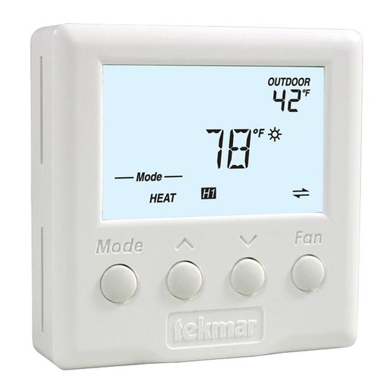
4 Thermostat 540
®
1
2
Information
Application
Brochure
Choose controls
Design your
to match
mechanical
application
applications
Overview
The following brochure describes how to wire the tekmarNet
of heat, one stage of cooling, and one fan.
Table of Contents:
Definitions .......................................................................2
Rough-In Wiring .............................................................2
Remove the Wiring Cover ..............................................3
Mounting the Thermostat ...............................................3
Wiring Symbols ...............................................................3
3
Layout
Brochure
Brochure
Rough-in
wiring
instructions
Cooling & Fan Power
4
Wiring
Brochure
Wiring and
installation of
specific control
4 (tN4) thermostat 540. The 540 has outputs for one stage
®
Fan
Cooling
tN4
Network
24 V (ac)
Power
Heating
Electrical Drawings ......................................................3-5
Wiring the Thermostat ....................................................6
Troubleshooting the Wiring .............................................7
Testing the Wiring ....................................................... 7, 8
Technical Data ................................................................8
1 of 8
5
6
Data
Brochure
Control settings
Record settings &
and sequence of
wiring details for
operation
future reference
1
2
3
4
DIP
Switch
Settings
© 2009
W 540
03/09
Job
Record
W 540 - 03/09
Advertisement
Table of Contents

Related Manuals for Tekmar tekmarNet 4 Thermostat 540


Summary of Contents for Tekmar tekmarNet 4 Thermostat 540
- Page 1 - Wiring Brochure W 540 tekmarNet 4 Thermostat 540 03/09 ® Information Application Layout Wiring Data Brochure Brochure Brochure Brochure Brochure Record Wiring and Control settings Choose controls Design your Rough-in Record settings & installation of and sequence of to match mechanical wiring wiring details for...
- Page 2 Defi nitions The following defined terms and symbols are used throughout this manual to bring attention to the presence of hazards of various risk levels, or to important information concerning the life of the product. – Caution: Refer to accompanying documents. –...
- Page 3 Remove the Wiring Cover To remove the wiring cover: Push tab Remove cover • Place a small slot screwdriver or similar tool into the slot located on the top of the thermostat. • While pushing against the plastic tab, pull the top of the front cover so that it pivots around the bottom edge of the thermostat’s base.
- Page 4 Electrical Application 540 E1 Description: 540 operates a hydronic heating system zone together with a Cooling System cooling system and fan. Reset Zone Menu Item Module Manager Test Heating System 540 tNt 1 Stage Cooling 1 Stage Fan Cooling Equipment Zone Manager ©...
- Page 5 Electrical Application 540 E2 Description: 540 operates a furnace and air conditioning system. Furnace and Air Conditioning System HVAC Equipment 1 Stage Heat 540 tNt 1 Stage Cooling 1 Stage Fan Install jumper wire from terminal 3 to terminal 5. daisy chain to other tN4 thermostats for communication...
- Page 6 Wiring the Thermostat: Power (24 V (ac)) Terminals 2, 3 Terminals R and C provide 24 V (ac) power. If a Zone Manager is used: • Connect C on the thermostat to C on the proper zone of the Zone Manager. •...
- Page 7 Fan 1 Contact Terminals 5, 7 Thermostat Terminals Rc and G are used to turn on the fan. • Rc-G is an isolated switch. No power is available from these terminals. • Connect Rc on the thermostat to R on the fan equipment. •...
- Page 8 Web Site: www.tekmarcontrols.com Product design, software and literature are Copyright © 2009 by: All specifications are subject to change without notice. 8 of 8 tekmar Control Systems Ltd. and tekmar Control Systems, Inc. Printed in Canada. W 540 - 03/09.
Need help?
Do you have a question about the tekmarNet 4 Thermostat 540 and is the answer not in the manual?
Questions and answers