Table of Contents
Advertisement
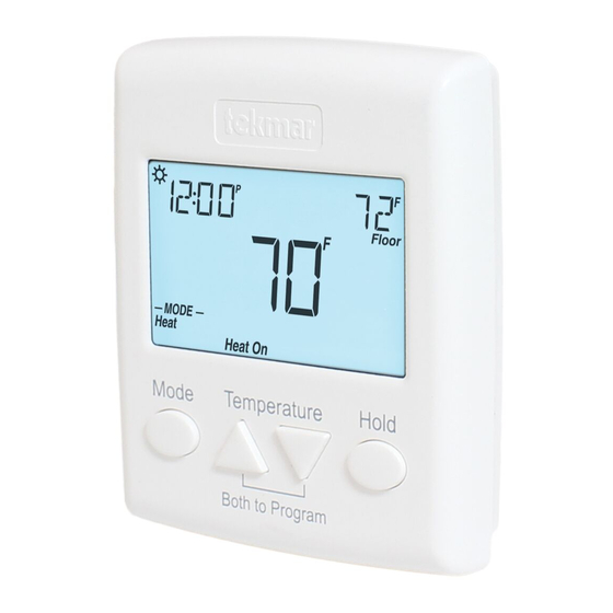
Programmable Thermostat 521
Installation & Operation Manual
Introduction
The Programmable Thermostat 521 is
designed for three different modes of
operation: single stage heating, two stages
of heating with a fan, or one stage of
heating and one stage of cooling with
a fan. Two auxiliary sensors may be
added to measure the floor, outdoor or
room temperature. A Slab Sensor 079 is
included to measure floor temperature to
protect the floor from overheating and
enhance comfort. The programmable
schedule supports either a 7 day or 24
hour schedule with 2 or 4 events per day.
A permanent temperature hold button
overrides the programmable schedule.
An optional Adaptor Plate 012 is available
to allow the thermostat to mount onto a
single gang electrical box.
A Watts Water Technologies Company
Energy Saving Features
• 7 Day Programmable Schedule
Additional Features
• Optimum Start
• Permanent Temperature Hold
• Radiant Floor Heating
• Two Stage Heating
• Cooling
• Fan
• Backlight
• Outdoor and Floor Temperature
Display
• Time Clock
• Four Hour Battery-free Clock
Backup
1 of 28
521 _ D
Zoning
Replaces: 01/14
© 2020
521_D - 12/20
12/20
Advertisement
Table of Contents

Related Manuals for Tekmar 521


Summary of Contents for Tekmar 521
- Page 1 Programmable Thermostat 521 Zoning Replaces: 01/14 Installation & Operation Manual Introduction The Programmable Thermostat 521 is Energy Saving Features designed for three different modes of • 7 Day Programmable Schedule operation: single stage heating, two stages of heating with a fan, or one stage of heating and one stage of cooling with a fan.
-
Page 2: Table Of Contents
Time Menu ........17 Schedule Menu ......18-19 Setup Menu ......20-21 Getting Started Congratulations on the purchase of your new tekmar thermostat. ® This manual will step through the complete installation, programming and sequence of operation for this control. At the back, there are tips for control and system troubleshooting. -
Page 3: Important Safety Information
Important Safety Information It is your responsibility to ensure that this control is safely installed according to all applicable codes and standards. tekmar is not responsible for damages resulting from improper installation and/or maintenance. To avoid serious personal injury and damage to the equipment: •... -
Page 4: Installation
---- - - ---- - - - - ----- - - - - - - - - - - - - - - - - - - - - - - - - - - - - - - - - - - Tools Required • tekmar or jeweller screwdriver • Wire Stripper •... -
Page 5: Mounting The Thermostat
Mounting The Thermostat Stud Adapter Plate 012 Thermostat Thermostat Base Front " (83 mm) Gang If a single gang box is used: • Adapter Plate 012 is required (sold separately). • Feed the wiring through the hole in the adaptor plate and the thermostat base. •... -
Page 6: Slab Sensor 079 Installation
Slab Sensor 079 Installation - - -- - - - - ---- - - - - - -- - - - - - - - - - - - - - - - - - - - - - - - - - - - - - - - - - - -- - - - - ---- - - - - - -- - - - - - - - - - - - - - - - - - - - - - - - - - - - - - - - - New Installations Thin-Set or Thin-Pour Applications... -
Page 7: Slab Sensor 079 Wiring
- - - - ---- - - - - - -- - - - - - - - - - - - - - - - - - - - - - - - - - - - - - - - - - - - - - ---- - - - - - -- - - - - - - - - - - - - - - - - - - - - - - - - - - - - - - - - - Retrofit Installations Tile Floor Coverings... -
Page 8: Slab Sensor 079 Testing
Slab Sensor 079 Testing A good quality test meter capable of measuring up to 5,000 kΩ (1 kΩ = 1000Ω) is required to measure the sensor resistance. In addition to this, the actual temperature must be measured with either a good quality digital thermometer, or if a thermometer is not available, a second sensor can be placed alongside the one to be tested and the readings compared. -
Page 9: Thermostat Wiring
Temperature vs. Resistance Table - Continued Temperature Resistance Temperature Resistance °F °C °F °C 5,828 1,538 5,210 1,403 4,665 1,281 4,184 1,172 3,760 1,073 3,383 3,050 2,754 2,490 2,255 2,045 1,857 1,689 Thermostat Wiring - --- - ---- - - ----- - - - - ---- - - - - - - - - - - - - - - - - - - - - - - - - - - - - - - - - - - --- - ---- - - ----- - - - - ---- - - - - - - - - - - - - - - - - - - - - - - - - - - - - - - - - - Zone Valve Field Jumper Required:... - Page 10 Thermostat Wiring -- -- - - - - --- - - - ---- - - - - - -- - - - - - - - - - - - - - - - - - - - - - - - - - - - - - - - - - -- -- - - - - --- - - - ---- - - - - - -- - - - - - - - - - - - - - - - - - - - - - - - - - - - - - - - - - Relay 003 Field Jumper Required:...
- Page 11 Thermostat Wiring --- - - - - - ----- - - - - --- - - - - - - - - - - - - - - - - - - - - - - - - - - - - - - - - - --- - - - - - ----- - - - - --- - - - - - - - - - - - - - - - - - - - - - - - - - - - - - - - - - Air Conditioner Field Jumper Required:...
-
Page 12: Testing The Thermostat Wiring
DC power supplies the voltage should measure between 10 to 30 V (dc). 3. If the voltage on the R and C wire terminations is continuous and the thermostat display is not on, the thermostat may have a fault. Contact your tekmar sales representative for assistance. -
Page 13: Switch Settings
-- - - - - - - - - - - - - - - - - - - - - - - - - - - - - - - - - - -- - - - - - - - - - - - - - - - - - - - - - - - - - - - - - - - - - Testing the Cooling Output Wiring Cooling is only available when the switch setting is set to H/C/F. -
Page 14: User Interface
User Interface Home Screen Floor MODE Room Floor Heat Cool Heat On Cool On Mode Button Hold Button Change operation Permanently from Heat, Cool overrides the and Off. schedule. Press hold to cancel. Symbols Description HEAT ON Schedule operating at the Heat is turned on. -
Page 15: Programmable Settings
Programmable Settings Navigation 1. Press and hold down both the buttons together to enter the Programming Menus. 2. While in the 3. While in the Programming Programming Menus, Menus, the MODE the HOLD button button changes changes function to PRGM function to become become the PRGM MENU... -
Page 16: Fan Menu
Fan Menu Setting Display Select if the fan should operate continuously (On) or only together with the heating or cooling equip- ment (Auto). Access Level: Installer, User Range: Auto or On Conditions: Only available when FAN MODE is not set to OFF and a room temperature sensor is Default: Auto available. -
Page 17: Time Menu
Set Temp Menu Setting Display SET FLOOR Set the floor heating temperature for the event. Range: OFF, 40 to 122°F Access Level: Installer, User (OFF, 4.5 to 50.0°C) Defaults Conditions: Sensor 1 or 2 is set to Floor and Air & floor sensors: 65°F (18.5°C) Schedule is set to On. -
Page 18: Schedule Menu
Schedule Menu (1 of 2) The schedule menu can operate on a 24 hour or 7 day repeating schedule. When a 24 hour schedule is selected, “SuMoTuWeThFrSa” is shown on the top of the screen to show that the event time applies to all days of the week. When a 7 day schedule is selected, each individual day of the week is shown with the event time. - Page 19 Schedule Menu (2 of 2) Setting Display SCHEDULE Select if the thermostat should change the temperature automatically using a programmable schedule. Access Level: Installer, User Range: OFF or On Conditions: Always available Default: OFF EVENT PER DAY Select either two or four scheduled events per day. Access Level: Installer, User Range: 2 or 4 Conditions: Schedule setting is set to On.
-
Page 20: Setup Menu
Default: AUTO TYPE Device Type number. Hold the button to view the software version. Access Level: Installer, User Range: 521 Conditions: Always available. Default: 521 SENSOR 1 Select the type of auxiliary sensor 1. Range: NONE, ROOM, FLOR Access Level: Installer... - Page 21 Setup Menu (2 of 2) Setting Display W2 RELAY Select if a second stage heat is available. Access Level: Installer Range: OFF or On Conditions: Available when switch setting 2 is set Default: OFF to 1H or 2H. W2 DELAY Select the time delay that the second stage must wait before turning on.
-
Page 22: Sequence Of Operation
Sequence of Operation Mode Button Operation Pressing the Mode button selects the operation of the thermostat to be either Heating, Cooling, or Off. The thermostat must be configured for heat/cool/fan operation in order for the cooling operation to be available. Heating Operation Heating is available when the Mode is set to Heat. -
Page 23: Cooling Operation
This operation is also recommended for rooms with hardwood floors. Setting floor minimum and maximum temperatures is a way of enhancing the comfort of the living space while protecting floor coverings. 90°F (32°C) Suggested maximum for all floor Feels hot to the touch types other than wood. -
Page 24: Fan Operation
Fan Operation A fan is available when the thermostat operates a forced air heating or cooling system. The fan can be set to On to allow air circulation through the building. This is useful if the air in the room is stale or if circulating cool air from a basement throughout a home can reduce the temperature in the upper floor without operating the cooling equipment. -
Page 25: Optimum Start
Optimum Start When a programmable schedule is selected, there is a time delay for the room to warm up from the temperature to the temperature. The thermostat has the option to use Optimum Start to predict the heat up rate of the room. When Optimum Start is set to On, the heating is started in advance to allow the room to reach the Set Room temperature at the time set in the programmable schedule. -
Page 26: Troubleshooting
The built-in air temperature sensor has an open circuit fault. Do not confuse this error with the auxiliary room sensor short circuit error. This error cannot be field repaired. Contact your wholesaler or tekmar Room sales representative for details on repair procedures. -
Page 27: Frequently Asked Questions
Thermostat must be in Mode Cool in Cooling not on Mode Off or Heat order to provide cooling. Technical Data Programmable Thermostat 521 Two Heat or Heat-Cool (Includes Sensor 079) Literature 521_A, 521_C, 521_D, 521_Q, 521_U Control Microprocessor control. This is not a safety (limit) control Packaged weight 0.6 lb. -
Page 28: Limited Warranty And Product Return Procedure
(24) months from the production date. The liability of tekmar under the Limited Warranty shall be limited to, at tekmar’s sole discretion: the cost of parts and labor provided by tekmar to repair defects in materials and / or workmanship of the defective product; or to the exchange of the defective product for a warranty replacement product;...
Need help?
Do you have a question about the 521 and is the answer not in the manual?
Questions and answers