Advertisement
Quick Links
Advertisement

Subscribe to Our Youtube Channel
Related Manuals for TMG TMG-MS2030LC


Summary of Contents for TMG TMG-MS2030LC
- Page 1 W W W . T M G I N D U S T R I A L . C O M P 0 / 24 T o l l F r e e : 1 - 8 7 7 - 7 6 1 - 2 8 1 9...
-
Page 2: Main Specifications
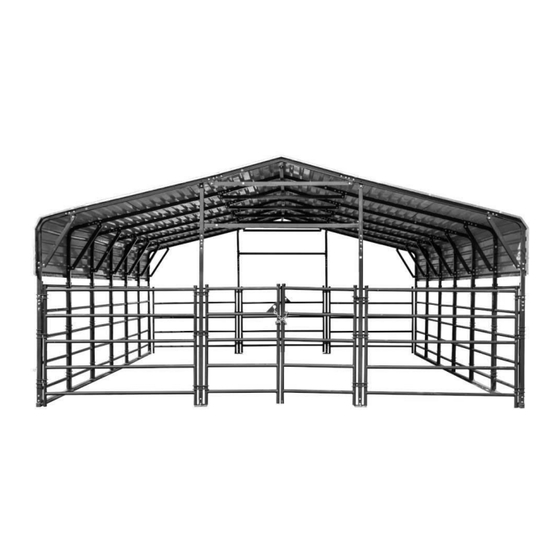
Main Specifications : Overall assembled size : W6 x L9 x H3.04 (m) / 20 x 30 x 10 (ft) Width : 6 m / 20ft Length : 9 m / 30 ft Ridge Peak Height : 3.04 m / 10 ft ... - Page 3 TMG-MS2030LC Part List Parts Graphical Description code Peak arch tube Middle rafter tube Middle rafter tube Shoulder tube Shoulder tube (middle) Sidewall tube Short casing Side edge crossbar (front and rear truss) Side edge crossbar (middle truss) Top cross bar A...
- Page 4 Foot tube (middle) Side reinforcement tube Reinforced tube mounting plate Metal sheet (front and rear truss) Metal sheet (middle truss) Edge protector Edge buckle Water plug Tube end water plug Steel cable mounting plate Side upper part fence Side lower part fence Front and rear upper part fence Front and rear lower part...
- Page 5 Right door Front door lower column tube Front door upper column tube Front door cross pull tube Baseplate Double fastener Single fastener Anchor hook ( M14x120mm ) Steel cable(3.9m) Expansion bolt (φ16x150mm) Waterproof silicon sealant Teroson statu Hex bolt M10x70mm Self tapping screw M5x25mm Rivet...
- Page 6 Sleeve Eyebolt Hex bolt M10x30mm Installation steps Step 1 : Review the whole structure and choose the proper installation site Refer to the foundation structure Figure 1, draw lines on the ground for positioning, all dimension lines are drawn from the center of the pipe to the center, and the diagonal X must be equal to Y.
- Page 7 Figure 1 Step 2 : Assemble all trusses The building includes 7 trusses : (1) front truss, (1) rear truss, (1) middle trusses and (4) other trusses. Parts used to install the front and rear truss in this step (refer to figure 2). ...
- Page 8 Figure 2 Parts used to install (1) middle trusses in this step (refer to figure 3). - (1) Peak arch tube (#1) - (2) Middle rafter tube (#2) - (2) Shoulder tube (#3A) - (2) Sidewall tube (#4) - (6) Short casing (#4A) - (1) Upper reinforcement tube (#6) - (2) Side reinforcement tube (#6D) - (12) Reinforced tube mounting plate (#6E)
- Page 9 Figure 3 Parts used to install (4) other trusses in this step (refer to figure 4). - (1x4) Peak arch tube (#1) - (2x4) Middle rafter tube (#2) - (2x4) Shoulder tube (#3) - (2x4) Sidewall tube (#4) - (6x4) Short casing (#4A) - (1x4) Upper reinforcement tube (#6) - (2x4) Side reinforcement tube (#6D) - (12x4) Reinforced tube mounting plate (#6E)
- Page 10 Figure 4 Lay down all (7) trusses on the ground when the assembly is all completed and before moving to next step (refer to figure 5). Figure 5 W W W . T M G I N D U S T R I A L . C O M P 9 / 24 T o l l F r e e : 1 - 8 7 7 - 7 6 1 - 2 8 1 9...
- Page 11 Step 3 : Assemble all trusses to the foundation pipe and connect them with (#17) bolts The front and rear trusses are installed with one side of (#12) Steel cable mounting plate facing outwards (refer to figure 6). Parts used in this step : ...
- Page 12 Install top cross bar A (#5C) and top cross bar B (#5D). Use (#30) and (#26) Hexagonal bolt fixation (refer to figure 7). Parts used in this step : - (5) Top cross bar A (#5C) - (1) Top cross bar B (#5D) - (5) Short casing (#4A) - (15) Hex bolt (#26) - (7) Hex bolt (#30)
- Page 13 Step 4 : Door column installation,the front and rear mounting methods are the same (refer to figure 8). - (2x2) Short casing (#4A) - (2x2) Front door lower column tube (#16) - (2x2) Front door upper column tube (#17) - (1x2) Front door cross pull tube (#18) - (16x2) Hex bolt M10x60mm (#26) - (2x2) Hex bolt M10x40mm (#33) Figure 8...
- Page 14 Step 5 : Assemble all the front and rear part fence as shown in (refer to figure 9). Parts used in this step : (4) Front and rear upper part fence (#14A) (4) Front and rear lower part fence (#14B) Figure 9 Step 6 : Install the front and rear door enclosure (refer to figure 10).
- Page 15 (12x2) Single fastener (#21) (18x2) Hex bolt M10x40mm (#33) Figure 10 Step 7 : Assemble all the side part fence as shown in (refer to figure 11). Parts used in this step : (12) Side upper part fence (#13A) (12) Side lower part fence (#13B) W W W .
- Page 16 Figure 11 Step 8 : Install fences on both sides Install the fence between the trusses, the left and right trusses and fences are fixed with single fastener (#21), middle trusses and fences are fixed with double fastener (#20), and locked with hex bolt (#33) , same installation method on both sides (refer to figure 12).
- Page 17 Figure 12 Step 9 : Install the color iron tile Before installation, ensure that the distance between centers of each collapse is 1500mm. Install the first row of colored steel tiles from the top end. The center of the colored steel tiles must be aligned with the midpoint of the top arch tube (you can mark the center of the top arch tube with a line).
- Page 18 Figure 13 Install all color iron tiles in turn, take the first colored steel tile at the top as the benchmark make sure that both ends of each color iron tile are aligned, and apply waterproof silicon sealant (#25) on the butt joint of both ends (refer to figure 14). W W W .
- Page 19 Figure 14 Step 10 : Install the front and rear edging strips Start to install the color steel tile edge protector (#9) from one side, and align one end with the color steel tile edge. The opening of the edge banding strip of the color steel tile shall be aligned with the end face of the color steel tile, and the bottom buckle can be pressed into place.
- Page 20 Figure 15 Install the edge buckle (#10) and the two raised card points of the edge buckle are aligned with the square holes at the interfaces of the two color steel tile edge bands, and then press the buckle in place. The front and rear installation methods are the same (refer to figure 16). W W W .
- Page 21 Figure 16 Step 11 : Connect the crossbar Install the side connecting crossbar, align (#5A) side edge crossbar with the binding strip, wrap the colored steel tile binding strip and the colored steel tile inside the opening of the connect the crossbar, and fix them on the (#4) sidewall tube with (#27) self tapping screw.
- Page 22 Parts used in this step : - (4) Side edge crossbar (#5A) - (8) Side edge crossbar (#5B) - (28) Self tapping screw (#27) Figure 17 Step 12 : Install the square pipe waterproof plug and anti-collision angle Put the waterproof plug into the square pipe head. Tear the 3M adhesive protective ...
- Page 23 Figure 18 Step 13 : Install eye bolts Drill holes from inside to outside where the middle truss has holes, through the thin metal sheet, Then install (#32) eyebolts (refer to figure 19). Parts used in this step : ...
- Page 24 Figure 19 Step 14 : Install the wire rope Select a suitable position to fix the expansion bolt of the draw hook one end of the wire rope onto the Steel cable (#23) mounting plate and eyebolt, and fix the other end to (#22) anchor hook of the draw hook, adjust the nut on the steel wire rope to tighten the steel wire rope (refer to figure 20).
- Page 25 Figure 20 Step 15 : Install the waterproof plug Install waterproof plug (#11A) on the pipe head at the upper end of all upper fence (#13A,#14A), left door (#15L) and right door (#15R) (refer to figure 21). Parts used in this step : ...
- Page 26 Figure 21 Now that your building is completely installed, we need to check all components and trusses to make sure the whole structure is rectangular. Check whether the connection of color steel tile fits. We provide (#28) rivets, which can be used to fix the color steel tiles where necessary, so that they can fit together to prevent water leakage.
- Page 27 sides will push inwards and could lead to a collapse. W W W . T M G I N D U S T R I A L . C O M P 26 / 24 T o l l F r e e : 1 - 8 7 7 - 7 6 1 - 2 8 1 9...
Need help?
Do you have a question about the TMG-MS2030LC and is the answer not in the manual?
Questions and answers