Advertisement
Quick Links
Advertisement

Subscribe to Our Youtube Channel
Related Manuals for TMG TMG-MSC1220F


Summary of Contents for TMG TMG-MSC1220F
- Page 1 www.tmgindustrial.com 0/14 TOLL FREE: 1-877-761-2819...
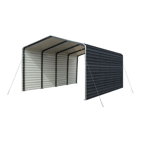
- Page 2 Main Specifications : Overall assembled size : W3.66 x L6 x H2.9 (m) / 12 x 19.7 x 9.5 (ft) Width : 3.66 m / 12ft Length : 6 m / 19.7ft Ridge peak height : 2.9 m / 9.5 ft Shoulder wall clearance height : 2.4 m / 7.9 ft Prior to assembly Please read the instructions carefully before installation.
- Page 3 TMG-MSC1220F Part List Parts Graphical Description Length code Peak arch tube L483mm Middle rafter tube L1280mm Shoulder tube L1034mm Sidewall tube L1524mm Short casing L198mm Metal sheet tile C W580xL1620mm (front and rear truss) Metal sheet tile D W580xL1600mm (middle truss)
- Page 4 Anchor hook φ16x120mm Steel cable φ6x3.3m Expansion bolt φ16 x 150mm Waterproof silicon sealant Caulking gun Hex bolt M10x60mm Self tapping screw 5.5x25mm Blind rivet φ3.2x5mm www.tmgindustrial.com 3/14 TOLL FREE: 1-877-761-2819...
- Page 5 Step 1 : Baseplate positioning and installation. The diagonal X and Y must be equal. Installation diagram of expansion bolt. Part www.tmgindustrial.com 4/14 TOLL FREE: 1-877-761-2819...
- Page 6 Step 2 : Install all trusses. Install front and rear trusses. Note : use (#18) at the links of (#3) and (#4) to reinforce the inner side Part Part 24x2 12x2 www.tmgindustrial.com 5/14 TOLL FREE: 1-877-761-2819...
- Page 7 Install other trusses. (3 trusses) Part Part 24x3 12x3 Lay down all (5) trusses on the ground as figure when the assembly is all completed and before moving to next step. www.tmgindustrial.com 6/14 TOLL FREE: 1-877-761-2819...
- Page 8 Step 3 : Put up the all trusses. The front and rear trusses are installed with one side of (#12) Steel cable mounting plate facing outwards. Part www.tmgindustrial.com 7/14 TOLL FREE: 1-877-761-2819...
- Page 9 Step 4 : Install the color iron tile. Before installation, ensure that the distance between centers of each collapse is 1500mm. Install the first row of colored iron tiles from the top end. The center of the colored steel tiles must be aligned with the midpoint of the top arch tube (you can mark the center of the top arch tube with a line).
- Page 10 Install the first color iron tile. Take the first colored iron tile at the top as the benchmark, ensure that both ends of each colored iron tile are aligned. Part www.tmgindustrial.com 9/14 TOLL FREE: 1-877-761-2819...
- Page 11 Install all color iron tiles in turn, make sure that both ends of each color iron tile are aligned, and apply waterproof silicon sealant (#16) on the butt joint of both ends . Part Part www.tmgindustrial.com 10/14 TOLL FREE: 1-877-761-2819...
- Page 12 Step 5 : Install the front and rear edging strips. Start to install the color iron tile edge protector (#9) from one side, and align one end with the color iron tile edge. The opening of the edge banding strip of the color iron tile shall be aligned with the end face of the color iron tile, and the bottom buckle can be pressed into place.
- Page 13 Install the edge buckle (#10), and the two raised card points of the Edge buckle are aligned with the square holes at the interfaces of the two color iron tile edge bands, and then press the buckle in place. The front and rear installation methods are the same.
- Page 14 Step 6 : Install the wire rope. Part Now that your building is completely installed, we need to check all components and trusses to make sure the whole structure is rectangular. Check whether the connection of color steel tile fits. We provide (#19) rivets, which can be used to fix the color steel tiles where necessary, so that they can fit together to prevent water leakage.
- Page 15 After the Installation Walk around and inspect the shelter periodically to make sure all components are still firmly secured and the whole shelter is well supported. Check all bolts and nuts as well as all connection points to make sure they are all in good position.
- Page 16 ATTENTION TO ENSURE THAT YOUR CARPORT SHED HAS BEEN SECURELY INSTALLED AND ITS WARRANTY VALIDITY, IT IS IMPORTANT TO READ THE FOLLOWING PAGES CAREFULLY.
- Page 17 As the owner of your product, it is important to take the necessary steps to ensure its stability and durability, especially in areas where heavy snow or high winds are common. Following these two steps will help prevent any damage due to snow or wind loads, and ensure that the product warranty remains valid.
Need help?
Do you have a question about the TMG-MSC1220F and is the answer not in the manual?
Questions and answers