Table of Contents
Advertisement
Quick Links
N6.2400 G-V
N6.2900 G-V
N7.3600 G-V
N7.4500 G-V
Operating instructions
For specialist installation engineers
Gas burners ........................................... 2-25
de, fr ..................................... 4200 1032 1400
it, nl ...................................... 4200 1032 1500
............................................. 4200 1032 0000
10/2010 - Art. Nr. 4200 1032 1300A
en
Advertisement
Table of Contents

Related Manuals for elco N6.2400 G-V


Summary of Contents for elco N6.2400 G-V
- Page 1 N6.2400 G-V N6.2900 G-V N7.3600 G-V N7.4500 G-V Operating instructions For specialist installation engineers Gas burners ........... 2-25 de, fr ........4200 1032 1400 it, nl ........4200 1032 1500 ..........4200 1032 0000 10/2010 - Art. Nr. 4200 1032 1300A...
-
Page 2: Table Of Contents
Operation Gas start-up mode, gas operating mode ....4 General safety functions........... 4 Equipment options............ 5 Elco Burners GmbH, Herbert- Automatic furnace controller LFL 1.../LGK....6 Liebsch-Straße 4a, 01796 Pirna, Gas valve VGD with SKP actuator......7 Germany, Gas valve MBC-VEF.......... -
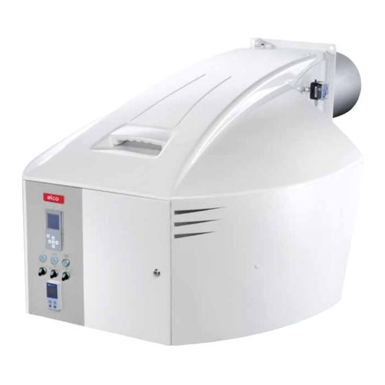
Page 3: Burner Description
Overview Burner description Power controller (option) Housing Gas inlet flange Gas damper (manual adjustment) Burner flame tube Integrated electrical cabinet Burner fixing flange Air intake box Hoisting eyes Air pressure switch Blower motor Y10 Actuator for air damper Furnace pressure take-off tube 10/2010 - Art. -
Page 4: Gas Start-Up Mode, Gas Operating Mode
Operation Gas start-up mode Gas operating mode General safety functions Gas start-up mode After the pre-ignition time, the main gas the burner to be operated at any desired As soon as the furnace system is valves are open and the gas comes out stage between its partial-load and full- required to supply heat, the burner from injectors where it is mixed in the... -
Page 5: Equipment Options
Operation Equipment options Please note! humidity, calorific value fluctuations, The gas outlet pressure (gas regulating etc.) and significantly reduce the air pressure) must always be less than the surplus required for calibration. gas inlet pressure but higher than the Reference value deviations are total pressure loss of the system. -
Page 6: Automatic Furnace Controller Lfl 1
O per at i on A ut om at i c f ur nace cont r ol l er LFL 1. . . / LG K . . . The LFL 1…/LGK... type controller is designed to control and monitor burners working according to a stepwise or modulating principle. -
Page 7: Gas Valve Vgd With Skp Actuator
O per at i on G as val ve VG D w i t h SK P act uat or G as val ve M B C - VEF Gas ball valve (option) Filter (under the cover) Gas manometer with push button (upstream) (option) Test burner with push button (option) -
Page 8: Boiler Lining For G-V Burner Burner Assembly
Assembly Boiler lining for G-V burner Burner assembly Boiler lining The burner lining must be installed right- angled to the burner tube. Possible trimming work (bevelling, rounding) as required for reverse boilers, for example, should done at a diameter not below 70% of the combustion chamber diameter. -
Page 9: Gas Connection
Assembly Gas connection Gas connection Gas connection pressure Leak test The gas lines and valves and A minimum connection pressure must The gas line upstream of the burner gas instruments group should be installed be available upstream of the burner gas valves and instruments group must be and taken into operation in accordance valve to ensure the proper functioning of... -
Page 10: Gas Manifold Pressure Take-Off Pipes
Assembly Gas manifold Pressure take-off pipes Gas train assembly • Check the correct position of the O-ring in the gas connecting flange. • Secure the gas train on the burner head so that the gas train coils are in the upper vertical position. •... -
Page 11: Checking, Assembling The Combustion Components11
Assembly Checking / assembling the combustion components Burner N6.2400 G-V N6.2900 G-V N7.3600 G-V 234,5 N7.4500 G-V Assembling the combustion components • Check that the O-Ring J1 is in the correct position in the gas elbow. • Check the adjustment settings of the ignition electrode as per the diagrams. -
Page 12: Gas Connection, Electrical Connection
Assembly Gas connection Electrical connection Checks before commissioning General regulations applying to the specified by the draft combustion gas connection ordinance. • The gas train must only be connected It is the responsibility of the fitter or his to the gas mains by a recognised representative to obtain approval for the specialist. -
Page 13: Working Cycle Test, Firing
• Fix and screw on the cover. 50 mbar 300 mbar ventilation, the burner comes on and operates at minimum power. N6.2400 G-V Air pressure switch • Check the following: N6.2900 G-V • See the paragraph entitled - the combustion N7.3600 G-V... -
Page 14: Actuator, Limit Switch Setting
C om m i ssi oni ng A ct uat or Li m i t sw i t ch set t i ng Important Once the pressure switches have been set, they must be protected to prevent settings from being altered. For example, this can be done by placing a spot of varnish on at least one of the screws on the equipment's protective... -
Page 15: Flame Sensor
C om m i ssi oni ng Flame sensor Ionisation monitoring During ionisation monitoring, it is Detection of the flame using an important that the signal is transmitted ionisation device. Flame detection is without wastage. The connection cable achieved using the conductivity and the must not lie adjacent to a multicore rectification effect of the hot flame cable. -
Page 16: Gas Pressure Switch Air Pressure Switch
Commissioning Gas pressure switch Air pressure switch Gas pressure switch GW...A5/A6 Gas pressure switch A5 Technical data: The gas pressure switch is designed to monitor the gas flow pressure. It can be Type of gas: used for monitoring either falling Gases according to DVGW Worksheet pressure (minimum) or rising pressure G 260/1, gas families 1, 2, 3... -
Page 17: Description
Gas valves and instruments group Description Specifications for the design, direction of flow (arrow on housing). construction and safety features of gas Prior to installation and operation, check Gas valves and instruments group type furnace systems in heating installations the valves and instruments and the are contained in DIN 4756 and TRD 412. -
Page 18: Basic Construction
Gas valves and instruments groups Basic construction The burner's scope of delivery may Low- and high-pressure gas trains • Gas pressure loss in the burner head, include a gas train. In this case, the If the outlet side of the regulator, i.e. •... - Page 19 Gas valves and instruments groups Basic construction Installation and mounting of the gas filter The gas filter may be installed in any desired position. Take care only to observe the direction of flow of the gas (arrow on filter housing). Make sure there is adequate clearance to facilitate the removal of the cover and replacement of the filter cartridge.
-
Page 20: Gas Valve Leakage Controller
Gas valves and instruments group Gas valve leakage controller Leakage controller VPS 504 S02 Working principle : Prior to each burner start-up, the controller checks for possible leaks between safety and main valves by increasing distribution pressure. Electrically, the leakage controller is serially connected between the thermostatic circuit and burner control and safety unit. -
Page 21: Maintenance
Servicing Maintenance Burner and boiler servicing must only Work recommended as part of annual - Flame monitor and automatic be carried out by a professionally burner maintenance: combustion control unit function check qualified heating engineer. The system - Burner test run, input measurement in - Commissioning the burner operator is advised to take out a the boiler room... - Page 22 Servicing Maintenance Filter replacement Checking the flue gas temperature • The filter element of the must be Precautions • Check the flue gas temperature at checked at least once a year and After any operation: check the regular intervals. replaced if clogged. combustion performance under real •...
-
Page 23: Exhaust Gas Test Trouble Shooting Instructions
Servicing Exhaust gas test Trouble shooting instructions Exhaust gas loss Natural Town Exhaust gas loss by way of free heat will L.P.G. occur as a result of the temperature difference between the fuel-air mixture 0,370 0,350 0,420 entering the furnace chamber and the 0,009 0,011 0,008... - Page 24 Servicing Exhaust gas test Trouble shooting instructions 6. Cleaning and lubricating 4. Mixing unit gives poor 5. Solenoid valve fails to open instructions combustion data Depending on the amount of dirt Cause Remedy introduced by the combustion air it will Cause Remedy Defective coil or...
-
Page 25: Operating Trouble
Servicing Operating trouble In case of operating trouble it should 3. Proper functional order and setting of Proceed with searching for the cause of be checked whether the system is in all control and safety instruments the trouble and eliminate it. Unlock the proper working order. - Page 26 10/2010 - Art. Nr. 4200 1032 1300A...
- Page 27 10/2010 - Art. Nr. 4200 1032 1300A...
- Page 28 Hotline ELCO Austria GmbH Aredstr.16-18 0810-400010 2544 Leobersdorf ELCO Belgium nv/sa Z.1 Researchpark 60 02-4631902 1731 Zellik ELCOTHERM AG Sarganserstrasse 100 0848 808 808 7324 Vilters ELCO GmbH Dreieichstr.10 0180-3526180 64546 Mörfelden-Walldorf ELCO Italia S.p.A. Via Roma 64 800-087887 31023 Resana (TV) ELCO Burners B.V.
Need help?
Do you have a question about the N6.2400 G-V and is the answer not in the manual?
Questions and answers