Table of Contents
Advertisement
Quick Links
OPERATOR'S MANUAL
INCLUDING: OPERATION, INSTALLATION AND MAINTENANCE
READ THIS MANUAL CAREFULLY BEFORE INSTALLING,
It is the responsibility of the employer to place this information in the hands of the operator. Keep for future reference.
INGERSOLL RAND COMPANY INC
34800 BENNETT DR, FRASER, MI 48026
www.gardnerdenver.com/en-us/mppumps
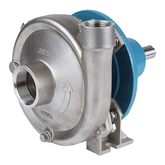
CHEMFLO® 1
(1-1/2" X 1")
OPERATING OR SERVICING THIS EQUIPMENT.
56C
CC Models
Hydraulic Models
Pedestal Models
© 2021
Figure 1
CHEMFLO 1
RELEASED:
(REV: A)
145TC
8-27-21
Advertisement
Table of Contents

Subscribe to Our Youtube Channel
Related Manuals for Ingersoll-Rand MP PUMPS CHEMFLO 1


Summary of Contents for Ingersoll-Rand MP PUMPS CHEMFLO 1
- Page 1 OPERATOR’S MANUAL CHEMFLO 1 RELEASED: 8-27-21 INCLUDING: OPERATION, INSTALLATION AND MAINTENANCE (REV: A) CHEMFLO® 1 (1-1/2” X 1”) READ THIS MANUAL CAREFULLY BEFORE INSTALLING, OPERATING OR SERVICING THIS EQUIPMENT. It is the responsibility of the employer to place this information in the hands of the operator. Keep for future reference. 145TC CC Models Hydraulic Models...
-
Page 2: General Description
GENERAL DESCRIPTION CHEMFLO 1: ChemFlo® 1 pumps utilize a semi-open impeller design to al- 1-1/2” x 1” End Suction Centrifugal Pump low for passage of larger solid sizes and a totally enclosed im- Made with high quality investment cast 316 stainless steel peller to meet high efficiency standards. -
Page 3: Operating And Safety Precautions
OPERATING AND SAFETY PRECAUTIONS READ, UNDERSTAND, AND FOLLOW THIS INFORMATION TO AVOID INJURY AND PROPERTY DAMAGE. Maximum temperatures are based on CAUTION EXCESSIVE AIR PRESSURE HAZARDOUS MATERIALS mechanical stress of seals and elastomers only. Cer- STATIC SPARK HAZARDOUS PRESSURE tain chemicals will significantly reduce maximum safe operating temperature. -
Page 4: Storage Precautions
STORAGE PRECAUTIONS BEARING INSTALLATION (PEDESTAL MODELS): Check the shaft to insure that it rotates freely. Shafts should Do not store filled with fluid at or below freezing temp of be aligned in accordance with the instructions of the cou- process fluid. pling manufacturer. -
Page 5: Motor Mounting
MOTOR MOUNTING TO ADJUST IMPELLER CLEARANCE: 1. Loosen the impeller drive sleeve Check rotation of the driver to be sure it coincides with the 2. Use a tool such as a screwdriver to push the impeller required rotation of the pump. When viewed from the driver back then reinsert the Assembly Shim. - Page 6 WORKING OF CENTRIFUGAL PUMP Hd = DISHCARGE HEAD DISCHARGE PIPE DISCHARGE Hs = SUCTION HEAD (NPSHr) OVER HEAD WATER TANK VALVE CASING SUCTION UNION PIPE FLANGE UNION FLANGE EYE OF IMPELLER SUCTION VALVE MINIMIZE LENGTH & AVOID SHARP BENDS NEAR INLET Figure 3 OPERATING INSTRUCTIONS WEAR AND INSPECTION POINTS...
-
Page 7: Seal Replacement Instructions
SEAL REPLACEMENT INSTRUCTIONS Make sure the shim is installed between the impeller and the wear plate. Do not remove the shim material before the drive DISASSEMBLE THE PUMP: sleeve clamp has been tightened to the motor drive shaft. INSTRUCTIONS FOR SET SCREW TYPE SEAL: Drain the system of liquid, break suction and discharge pipe unions, and, if necessary, remove all piping from the suction Do not remove the seal retaining clips. - Page 8 PARTS LIST / CHEMFLO 1 CC (56C AND 145TC) Enclosed Impeller For 145 TC Motors Figure 4 PARTS LIST / CHEMFLO 1 CC (56C AND 145TC) Item Description Qty Part No. Item Description Qty Part No. (size) (size) Impeller 34709 CF8M SS Pipe Plug ( 21255...
- Page 9 PARTS LIST / CHEMFLO 1 HYDRAULIC (0.22 AND 0.37) Enclosed Impeller Figure 5 PARTS LIST / CHEMFLO 1 HYDRAULIC (0.22 AND 0.37) Item Description Qty Part No. Item Description Qty Part No. (size) (size) Drive Sleeve 35753 316 SS Pipe Plug 21255 316 SS (1/8"...
- Page 10 PARTS LIST / CHEMFLO 1 PEDESTAL Enclosed Impeller Figure 6 PARTS LIST / CHEMFLO 1 PEDESTAL Item Description Qty Part No. Item Description Qty Part No. (size) (size) Drive Sleeve 29785 316 SS Pipe Plug ( 21255 316 SS (56C) 1/8"...
-
Page 11: Service Kits
SERVICE KITS PUMP MODEL PUMP DESCRIPTION SEAL KIT BEARING KIT IMPELLER MP50731 CF1PMP SS:1.5-1 56C 3.6 T-2 SSC MP51274 #N/A MP30233 MP34027 CF1PMP SS:1.5-1 56C 3.6 T-2100 MP51271 #N/A MP30233 MP31114 CF1PMP SS:1.5-3 56C 3.6 T-2100 MP51271 #N/A MP30233 MP39628 CF1PMP SS:1.5-3 56C 3.6 T-9 TFE MP51273 #N/A... - Page 12 SERVICE KITS PUMP MODEL PUMP DESCRIPTION SEAL KIT BEARING KIT IMPELLER MP30885 CF1PMP SS:3-3 56C 6.0 T-2100 MP51271 #N/A MP29910 MP38238 CF1PMP SS:3-3 56C 6.0 T-2100 BALDOR MP51271 #N/A MP29910 MP31465 CF1PMP SS:3-3 56C 6.0 T-9 MP51273 #N/A MP29910 MP37189 CF1PMP SS:3-3 56C 60/50 5.30 T-9 MP51273 #N/A...
-
Page 13: Dimensional Data
DIMENSIONAL DATA CF1 PUMPAK FOR 56C FOOTLESS MOTOR Figure 7 CF1 PUMPAK FOR 145TC MOTOR WITH FOOT Figure 8 CHEMFLO 1 (en) Page 13 of 16... - Page 14 DIMENSIONAL DATA CF1 0.22 DISP MOTOR Figure 9 CF1 0.37 DISP MOTOR Figure 10 CF1 PED Figure 11 Page 14 of 16 CHEMFLO 1 (en)
-
Page 15: Troubleshooting
TROUBLESHOOTING PROBLEM PROBABLE CAUSE REMEDY 1. Reprime pump, check that pump and 1. Pump not primed. there are no obstructions in the suc- tion line. 2. Discharge valve closed 2. Check discharge valve. 3. Suction line clogged. 3. Remove obstructions. 4. - Page 16 PROBLEM PROBABLE CAUSE REMEDY 1. Improper pump/driver alignment. 1. Align shafts. 2. Partly clogged impeller causing 2. Back-flush pump to clean impeller. imbalance. 3. Broken or bent impeller or shaft. 3. Replace as required. 4. Tighten bolts of pump and motor or 4.
Need help?
Do you have a question about the MP PUMPS CHEMFLO 1 and is the answer not in the manual?
Questions and answers