Table of Contents
Advertisement
Advertisement
Table of Contents

Related Manuals for Husqvarna FC 250 EU 2015


Summary of Contents for Husqvarna FC 250 EU 2015
- Page 1 OWNER'S MANUAL 2015 FC 250 EU FC 250 US Art. no. 3402019en...
- Page 3 Husqvarna accepts no liability for deliv- ery options, deviations from illustrations and descriptions, as well as misprints and other errors.
-
Page 4: Table Of Contents
TABLE OF CONTENTS TABLE OF CONTENTS RIDING INSTRUCTIONS........... 20 MEANS OF REPRESENTATION ......... 4 Checks and maintenance before putting into Symbols used ............4 operation ............. 20 Formats used............4 Starting ..............20 SAFETY ADVICE ..............5 Starting off ............21 Use definition - intended use........ - Page 5 TABLE OF CONTENTS 11.25 Installing the air filter ......... 44 15.4 Draining the coolant ......... 74 11.26 Cleaning the air filter and air filter box ....44 15.5 Refilling coolant ..........75 11.27 Sealing the air filter box ........45 TUNING THE ENGINE ............
-
Page 6: Means Of Representation
All work marked with this symbol requires specialist knowledge and technical understanding. In the interest of your own safety, have these jobs performed by an authorized Husqvarna workshop. There, your motorcycle will be opti- mally cared for by specially trained experts using the special tools required. -
Page 7: Safety Advice
SAFETY ADVICE Use definition - intended use Husqvarna sport motorcycles are designed and built to withstand the normal stresses and strains of competitive use. The motorcycles comply with currently valid regulations and categories of the top international motorsport organizations. Info The motorcycle may only be used in closed off areas remote from public road traffic. -
Page 8: Protective Clothing
Keep the Owner's Manual in an accessible place to enable you to refer to it as needed. If you would like to know more about the vehicle or have questions on the material you read, please contact an authorized Husqvarna dealer. -
Page 9: Important Notes
Manufacturer and implied warranty The work prescribed in the service schedule must be carried out by an authorized Husqvarna workshop only and confirmed in the cus- tomer's service & warranty booklet and in the Husqvarna dealer.net; otherwise, all warranty claims will be void. No warranty claims can be considered for damage resulting from manipulations and/or alterations to the vehicle. -
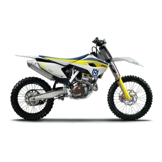
Page 10: View Of Vehicle
VIEW OF VEHICLE View of vehicle, front left side (example) M00236-10 Hand brake lever ( p. 11) Fork compression adjustment Clutch lever ( p. 11) Filler cap Cold start button ( p. 13) Shift lever ( p. 14) Engine number ( p. -
Page 11: View Of Vehicle, Rear Right Side (Example)
VIEW OF VEHICLE View of vehicle, rear right side (example) M00237-10 Kill switch ( p. 11) Electric starter button ( p. 11) Throttle grip ( p. 11) Fork rebound adjustment Shock absorber rebound adjustment Shock absorber compression adjustment Level viewer, engine oil Foot brake lever ( p. -
Page 12: Serial Numbers
SERIAL NUMBERS Chassis number The chassis number is stamped on the right side of the steering head. 401945-10 Type label The type label is fixed to the front of the steering head. 401946-10 Engine number The engine number is stamped on the left side of the engine under the engine sprocket. -
Page 13: Controls
CONTROLS Clutch lever The clutch lever is fitted on the left side of the handlebar. The clutch is hydraulically operated and self-adjusting. B01826-10 Hand brake lever Hand brake lever is located on the right side of the handlebar. The hand brake lever is used to activate the front brake. -
Page 14: Map-Select Switch For The Basic Setting
CONTROLS Map‑Select switch for the basic setting The Map‑Select switch for the basic setting is fitted under the seat. Possible states Soft – The mapping with reduced peak performance for better rideability is activated. ADVANCED – The mapping for performance with a very direct response is activated. -
Page 15: Closing The Filler Cap
CONTROLS – Turn filler cap counterclockwise and lift it off. M00241-10 6.10 Closing the filler cap – Mount filler cap and turn it clockwise until the fuel tank is tightly closed. Info Run the fuel tank breather hose ... -
Page 16: Idle Speed Adjusting Screw
CONTROLS 6.12 Idle speed adjusting screw The idle setting of the throttle valve body has a big influence on the vehicle's starting behavior, on stable idling, and on vehicle response when the throttle is opened. This means that an engine with a correctly set idle speed is easier to start than if the idle is set wrongly. -
Page 17: Plug-In Stand
CONTROLS 6.15 Plug-in stand The holder for the plug-in stand is the left side of the wheel spindle. The plug-in stand is used to park the motorcycle. Info Remove the plug-in stand before starting on a trip. 0 0 1 402001-10... -
Page 18: Preparing For Use
When using your motorcycle, remember that others may feel disturbed by excessive noise. – Make sure that the pre-delivery inspection work has been carried out by an authorized Husqvarna workshop. You receive a delivery certificate and the service record at vehicle handover. -
Page 19: Running In The Engine
PREPARING FOR USE – Do not exceed the overall maximum permitted weight and the axle loads. Guideline Maximum permissible overall weight 335 kg (739 lb.) Maximum permissible front axle load 145 kg (320 lb.) Maximum permissible rear axle load 190 kg (419 lb.) –... -
Page 20: Preparing For Rides On Wet Sand
PREPARING FOR USE – Fit a sand protection device on the air filter. Sand protection device for air filter (59006922000) Info Observe the Husky Power fitting instructions. B00436-01 – Clean the chain. – Fit the steel sprocket. Do not grease the chain. –... -
Page 21: Preparing For Rides At High Temperatures And Low Speeds
PREPARING FOR USE – Fit the steel sprocket. – Clean the motorcycle. ( p. 82) – Straighten bent radiator fins carefully. 600868-01 Preparing for rides at high temperatures and low speeds – Adjust the secondary drive to the road conditions. Info The engine oil heats up quickly when the clutch is operated frequently due to an excessively high secondary drive. -
Page 22: Riding Instructions
RIDING INSTRUCTIONS Checks and maintenance before putting into operation Info Before every trip, check the condition of the vehicle and ensure that it is safe to operate. The vehicle must be in perfect technical condition when used. – Check the engine oil level. ( p. -
Page 23: Starting Off
Do not change into a low gear at high engine speed. The engine races and the rear wheel can lock up. Info If you hear unusual noises while riding, stop immediately, switch off the engine and contact an authorized Husqvarna workshop. First gear is used for starting off or for steep inclines. -
Page 24: Transport
– In some countries and regions, the available fuel quality and cleanliness may not be sufficient. This will result in problems with the fuel system. (Your authorized Husqvarna workshop will be glad to help.) – Only refuel with clean fuel that meets the specified standards. - Page 25 RIDING INSTRUCTIONS – Switch off the engine. – Open the filler cap. ( p. 12) – Fill the fuel tank with fuel up to measurement Guideline 35 mm (1.38 in) Measurement of Total fuel tank 7.5 l (1.98 US gal) Super unleaded (ROZ 95/RON 95/PON capacity, approx.
-
Page 26: Service Schedule
Final check: Check the vehicle for operating safety and take a test ride. ○ ● ● ● Read out the fault memory using after the test ride the Husqvarna diagnostics tool. ○ ● ● ● Make the service entry in Husqvarna Dealer.net and in the service booklet. -
Page 27: Service Work (As Additional Order)
SERVICE SCHEDULE Service work (as additional order) Annually Every 100 operating hours - corresponds to about 700 liters of fuel (185 US gal) Every 50 operating hours - corresponds to about 350 liters of fuel (92.5 US gal) Every 40 operating hours - corresponds to about 280 liters of fuel (74 US gal) Once after 20 operating hours Once after 10 operating hours ●... -
Page 28: Tuning The Chassis
Caution Danger of accidents Disassembly of pressurized parts can lead to injury. – The shock absorber is filled with high density nitrogen. Adhere to the description provided. (Your authorized Husqvarna work- shop will be glad to help.) Info The low-speed setting can be seen during the slow to normal compression of the shock absorber. -
Page 29: Adjusting The High-Speed Compression Damping Of The Shock Absorber
Caution Danger of accidents Disassembly of pressurized parts can lead to injury. – The shock absorber is filled with high density nitrogen. Adhere to the description provided. (Your authorized Husqvarna work- shop will be glad to help.) Info The high-speed setting can be seen during the fast compression of the shock absorber. -
Page 30: Measuring Rear Wheel Sag Unloaded
TUNING THE CHASSIS 10.6 Measuring rear wheel sag unloaded Preparatory work – Raise the motorcycle with the lift stand. ( p. 33) Main work – Measure the distance – as vertical as possible – between the rear axle and a fixed point, for example, a mark on the side cover. -
Page 31: Adjusting The Spring Preload Of The Shock Absorber
Caution Danger of accidents Disassembly of pressurized parts can lead to injury. – The shock absorber is filled with high density nitrogen. Adhere to the description provided. (Your authorized Husqvarna work- shop will be glad to help.) Info Before changing the spring preload, make a note of the present setting, e.g., by measuring the length of the spring. -
Page 32: Checking The Basic Setting Of The Fork
TUNING THE CHASSIS Main work – Choose and mount a suitable spring. Guideline Spring rate Weight of rider: 65… 75 kg (143… 51 N/mm (291 lb/in) 165 lb.) Weight of rider: 75… 85 kg (165… 54 N/mm (308 lb/in) 187 lb.) Weight of rider: 85…... -
Page 33: Adjusting The Rebound Damping Of The Fork
TUNING THE CHASSIS Info Turn clockwise to increase damping; turn counterclockwise to reduce damp- ing. 10.13 Adjusting the rebound damping of the fork Info The hydraulic rebound damping determines the fork suspension behavior. – Turn the red adjusting screw all the way clockwise. - Page 34 TUNING THE CHASSIS – Position the handlebar. Info Make sure the cables and wiring are positioned correctly. – Position the handlebar clamps. Mount and tighten screws evenly. Guideline Screw, handlebar clamp 20 Nm (14.8 lbf ft)
-
Page 35: Service Work On The Chassis
SERVICE WORK ON THE CHASSIS 11.1 Raising the motorcycle with the lift stand Note Danger of damage The parked vehicle may roll away or fall over. – Always place the vehicle on a firm and even surface. – Raise the motorcycle at the frame underneath the engine. The wheels must no longer touch the ground. -
Page 36: Cleaning The Dust Boots Of The Fork Legs
SERVICE WORK ON THE CHASSIS 11.4 Cleaning the dust boots of the fork legs Preparatory work – Raise the motorcycle with the lift stand. ( p. 33) – Remove the fork protector. ( p. 34) Main work – Push dust boot ... -
Page 37: Removing The Fork Legs
SERVICE WORK ON THE CHASSIS 11.7 Removing the fork legs Preparatory work – Raise the motorcycle with the lift stand. ( p. 33) – Remove the front wheel. p. 65) Main work – Remove screws and take off the clamp. –... -
Page 38: Removing The Lower Triple Clamp
SERVICE WORK ON THE CHASSIS 11.9 Removing the lower triple clamp Preparatory work – Raise the motorcycle with the lift stand. ( p. 33) – Remove the front wheel. p. 65) – Remove the fork legs. p. 35) – Remove the start number plate. ( p. - Page 39 SERVICE WORK ON THE CHASSIS – Position the fork legs. Bleeder screws face forward. Info The rebound damping is located in the right fork leg (red adjusting screw). The compression damping is located in the left fork leg (white adjusting screw).
-
Page 40: Checking The Steering Head Bearing Play
Danger of accidents Unstable vehicle handling from incorrect steering head bearing play. – Adjust the steering head bearing play without delay. (Your authorized Husqvarna workshop will be glad to help.) Info If the bike is ridden with play in the steering head bearing, the bearing and the bearing seats in the frame can become damaged over time. -
Page 41: Greasing The Steering Head Bearing
SERVICE WORK ON THE CHASSIS – Remove the motorcycle from the lift stand. ( p. 33) – Mount the handlebar cushion. 11.13 Greasing the steering head bearing – Remove the lower triple clamp. p. 36) – Install the lower triple clamp. p. -
Page 42: Installing The Front Fender
SERVICE WORK ON THE CHASSIS Main work – Remove screws . Remove the front fender. B01876-10 11.17 Installing the front fender Main work – Position the front fender. Mount and tighten screws Guideline Remaining screws, chassis 10 Nm (7.4 lbf ft) B01876-10 Finishing work... -
Page 43: Installing The Shock Absorber
SERVICE WORK ON THE CHASSIS – Press angle lever toward the rear. – Press linkage lever downward. B01878-10 – Detach springs Spring hooks (50305017000) – Remove screw and take off the manifold. M00300-10 – Remove screws on both sides. -
Page 44: Removing The Seat
SERVICE WORK ON THE CHASSIS – Position the rear frame. – Mount and tighten screws on both sides. Guideline Screw, subframe 30 Nm Loctite ® 2701™ (22.1 lbf ft) – Remove screws on both sides. – Mount and tighten screws on both sides. -
Page 45: Mounting The Seat
SERVICE WORK ON THE CHASSIS 11.21 Mounting the seat – Hook in the front of the seat at the collar bushing of the fuel tank, lower it at the rear and simultaneously push it forward. – Make sure that the seat is correctly locked in. –... -
Page 46: Installing The Air Filter
SERVICE WORK ON THE CHASSIS 11.25 Installing the air filter Main work – Mount the clean air filter on the air filter support. – Grease the air filter in area Long-life grease ( p. 95) 101351-10 – Insert both parts together, position them, and fasten them using air filter holder ... -
Page 47: Sealing The Air Filter Box
SERVICE WORK ON THE CHASSIS 11.27 Sealing the air filter box Preparatory work – Remove the air filter box lid. ( p. 43) Main work – Seal the air filter box in the marked area 401559-01 Finishing work – Install the air filter box lid. -
Page 48: Removing The Right Side Cover
SERVICE WORK ON THE CHASSIS Preparatory work – Remove the right side cover. ( p. 46) – Remove the main silencer. ( p. 45) Main work – Remove all screws from the main silencer. – Take off silencer cap and O-ring –... -
Page 49: Removing The Fuel Tank
SERVICE WORK ON THE CHASSIS 11.33 Removing the fuel tank Danger Fire hazard Fuel is highly flammable. – Never refuel the vehicle near open flames or burning cigarettes, and always switch off the engine first. Be careful that no fuel is spilt, especially on hot vehicle components. Clean up spilt fuel immediately. –... -
Page 50: Installing The Fuel Tank
SERVICE WORK ON THE CHASSIS – Pull both spoilers off of the sides of the radiator bracket and lift off the fuel tank. M00269-10 11.34 Installing the fuel tank Danger Fire hazard Fuel is highly flammable. – Never refuel the vehicle near open flames or burning cigarettes, and always switch off the engine first. Be careful that no fuel is spilt, especially on hot vehicle components. -
Page 51: Checking For Chain Dirt Accumulation
SERVICE WORK ON THE CHASSIS 11.35 Checking for chain dirt accumulation – Check the chain for coarse dirt accumulation. » If the chain is very dirty: – Clean the chain. ( p. 49) 400678-01 11.36 Cleaning the chain Warning Danger of accidents Oil or grease on the tires reduces their grip. –... -
Page 52: Adjusting The Chain Tension
SERVICE WORK ON THE CHASSIS Main work – Pull the chain at the end of the chain sliding component upwards to measure chain tension Info The lower chain section must be taut. Chain wear is not always even, so you should repeat this measurement at different chain positions. -
Page 53: Checking The Chain, Rear Sprocket, Engine Sprocket And Chain Guide
SERVICE WORK ON THE CHASSIS (FC 250 US) – Loosen nut – Loosen nuts – Adjust the chain tension by turning adjusting screws left and right. Guideline Chain tension 55… 58 mm (2.17… 2.28 in) Turn adjusting screws on the left and right so that the markings on the left and right chain adjusters are in the same position relative to reference marks... - Page 54 SERVICE WORK ON THE CHASSIS – Check the chain sliding guard for wear. » If the bottom edge of the chain pin is in line with or below the chain sliding guard: – Change the chain sliding guard. – Check that the chain sliding guard is firmly seated. »...
-
Page 55: Checking The Frame
If the swingarm shows signs of damage, cracking, or deformation: – Change the swingarm. Info A damaged swingarm must always be changed. Repair of the swingarm is not authorized by Husqvarna. 500285-01 11.42 Checking the throttle cable routing Preparatory work –... -
Page 56: Checking The Rubber Grip
SERVICE WORK ON THE CHASSIS 11.43 Checking the rubber grip – Check the rubber grips on the handlebar for damage and wear and to ensure they are firmly seated. » If a rubber grip is damaged, worn or loose: – Change and secure the rubber grip. -
Page 57: Changing The Hydraulic Clutch Fluid
SERVICE WORK ON THE CHASSIS 11.47 Changing the hydraulic clutch fluid Warning Environmental hazard Hazardous substances cause environmental damage. – Oil, grease, filters, fuel, cleaners, brake fluid, etc., should be disposed of as stipulated in applicable regulations. – Move the clutch fluid reservoir mounted on the handlebar to a horizontal position. –... -
Page 58: Brake System
Danger of accidents Reduced braking efficiency due to worn brake disc(s). – Change the worn brake disc(s) without delay. (Your authorized Husqvarna workshop will be glad to help.) – Check the thickness of the front and rear brake discs at several places on the disk to ... -
Page 59: Checking The Front Brake Fluid Level
Husqvarna workshop will be glad to help.) Warning Danger of accidents Reduced braking efficiency due to old brake fluid. – Change the brake fluid of the front and rear brake according to the service schedule. (Your authorized Husqvarna workshop will be glad to help.) Preparatory work –... -
Page 60: Checking The Front Brake Linings
Warning Danger of accidents Reduced braking efficiency due to old brake fluid. – Change the brake fluid of the front and rear brake according to the service schedule. (Your authorized Husqvarna workshop will be glad to help.) Warning Environmental hazard Hazardous substances cause environmental damage. - Page 61 BRAKE SYSTEM Info Never use DOT 5 brake fluid! It is silicone-based and purple in color. Oil seals and brake lines are not designed for DOT 5 brake fluid. Avoid contact between brake fluid and painted parts. Brake fluid attacks paint! Use only clean brake fluid from a sealed container.
-
Page 62: Checking The Free Travel Of Foot Brake Lever
BRAKE SYSTEM – Add brake fluid to level Guideline 5 mm (0.2 in) Dimension (brake fluid level below top edge of container) Brake fluid DOT 4 ( p. 93) – Position cover with membrane – Mount and tighten screws Info Clean up overflowed or spilt brake fluid immediately with water. -
Page 63: Checking The Rear Brake Fluid Level
Husqvarna workshop will be glad to help.) Warning Danger of accidents Reduced braking efficiency due to old brake fluid. – Change the brake fluid of the front and rear brake according to the service schedule. (Your authorized Husqvarna workshop will be glad to help.) Preparatory work –... -
Page 64: Checking The Rear Brake Linings
Warning Danger of accidents Reduced braking efficiency due to old brake fluid. – Change the brake fluid of the front and rear brake according to the service schedule. (Your authorized Husqvarna workshop will be glad to help.) Warning Environmental hazard Hazardous substances cause environmental damage. -
Page 65: Changing The Rear Brake Linings
Warning Danger of accidents Reduced braking efficiency due to old brake fluid. – Change the brake fluid of the front and rear brake according to the service schedule. (Your authorized Husqvarna workshop will be glad to help.) Warning Environmental hazard Hazardous substances cause environmental damage. - Page 66 BRAKE SYSTEM – Insert the new brake linings, insert pin , and mount cotter pins Info Always change the brake linings in pairs. Info Make sure that decoupling plate is mounted on the piston side of the brake lining.
-
Page 67: Wheels, Tires
WHEELS, TIRES 13.1 Removing the front wheel Preparatory work – Raise the motorcycle with the lift stand. ( p. 33) Main work – Press the brake caliper onto the brake disc by hand in order to push back the brake pistons. -
Page 68: Removing The Rear Wheel
WHEELS, TIRES – Mount and tighten screw Guideline Screw, front wheel spindle M20x1.5 35 Nm (25.8 lbf ft) – Activate the hand brake lever multiple times until the brake linings are in contact with the brake disc. – Remove the motorcycle from the lift stand. ( p. -
Page 69: Installing The Rear Wheel
WHEELS, TIRES Info Do not operate the foot brake when the rear wheel is removed. Always lay the wheel down in such a way that the brake disc is not dam- aged. – Remove spacers M00295-10 13.4 Installing the rear wheel Warning Danger of accidents Reduced braking efficiency due to oil or grease on the brake discs. -
Page 70: Checking The Tire Condition
DOT code. The first two digits indi- cate the week of manufacture and the last two digits the year of manufacture. Husqvarna recommends that the tires be changed after 5 years at the latest, regardless of the actual state of wear. -
Page 71: Checking The Tire Air Pressure
Danger of accidents Instable handling due to incorrect spoke tension. – Ensure that the spoke tension is correct. (Your authorized Husqvarna workshop will be glad to help.) Info A loose spoke causes wheel imbalance and rapidly leads to more loose spokes. -
Page 72: Electrical System
ELECTRICAL SYSTEM 14.1 Removing the battery Warning Risk of injury Battery acid and battery gases cause serious chemical burns. – Keep batteries out of the reach of children. – Wear suitable protective clothing and goggles. – Avoid contact with battery acid and battery gases. –... -
Page 73: Recharging The Battery
– Do not dispose of batteries with the household waste. Dispose of a defective battery in an environmentally friendly manner. Give it to your Husqvarna dealer or to a disposal center for used batteries. Warning Environmental hazard Hazardous substances cause environmental damage. -
Page 74: Changing The Main Fuse
ELECTRICAL SYSTEM 14.4 Changing the main fuse Warning Fire hazard The electrical system can be overloaded if the wrong fuses are used. – Use only fuses with the prescribed amperage. Never by-pass or repair fuses. Info The main fuse protects all power consumers of the vehicle. It is located in the starter relay housing under the air filter box lid. Preparatory work –... -
Page 75: Cooling System
COOLING SYSTEM 15.1 Cooling system Water pump in the engine circulates the coolant. The pressure resulting from the warming of the cooling system is regulated by a valve in radiator cap . This ensures that operating the vehicle at the specified coolant temper- ature will not result in a risk of malfunctions. -
Page 76: Checking The Coolant Level
COOLING SYSTEM 15.3 Checking the coolant level Warning Danger of scalding During motorcycle operation, the coolant gets very hot and is under pressure. – Do not remove the radiator cap, radiator hoses or other cooling system components when the engine is hot. Allow the engine and cooling system to cool down. -
Page 77: Refilling Coolant
COOLING SYSTEM 15.5 Refilling coolant Warning Danger of poisoning Coolant is poisonous and a health hazard. – Coolant must not come into contact with the skin, eyes, or clothing. If contact occurs with the eyes, rinse with water imme- diately and contact a physician. Immediately clean contaminated areas on the skin with soap and water. If coolant is swal- lowed, contact a physician immediately. -
Page 78: Tuning The Engine
TUNING THE ENGINE 16.1 Checking the play in the throttle cable – Check the throttle grip for smooth operation. – Move the handlebar to the straight-ahead position. Turn the throttle grip back and forth slightly and determine the play in throttle cable ... -
Page 79: Adjusting The Idle Speed
TUNING THE ENGINE 16.3 Adjusting the idle speed – Run the engine until warm. – Set the desired idle speed by turning the idle speed adjusting screw Guideline Idle speed 2,250… 2,350 rpm Tachometer (45129075000) Info Turn counterclockwise to decrease the idle speed. Turn clockwise to increase the idle speed. -
Page 80: Service Work On The Engine
SERVICE WORK ON THE ENGINE 17.1 Changing the fuel screen Danger Fire hazard Fuel is highly flammable. – Never refuel the vehicle near open flames or burning cigarettes, and always switch off the engine first. Be careful that no fuel is spilt, especially on hot vehicle components. Clean up spilt fuel immediately. –... -
Page 81: Changing The Engine Oil And Oil Filter, Cleaning The Oil Screen
SERVICE WORK ON THE ENGINE The engine oil is at a level between the middle and upper edge of the level viewer. » If the engine oil is not up to the middle of the level viewer: –... -
Page 82: Adding Engine Oil
SERVICE WORK ON THE ENGINE – Remove screws . Remove the oil filter cover with the O-ring. S00475-10 – Pull oil filter out of the oil filter housing. Circlip pliers reverse (51012011000) – Completely drain the engine oil. –... - Page 83 SERVICE WORK ON THE ENGINE – Remove the oil filler plug with the O-ring from the clutch cover. – Add the same engine oil that was used when the motor was changed. Engine oil (SAE 10W/50) ( p. 93) Info For optimal performance of the engine oil, do not mix different types of engine oil.
-
Page 84: Cleaning, Care
CLEANING, CARE 18.1 Cleaning the motorcycle Note Material damage Damage and destruction of components by high-pressure cleaning equipment. – When cleaning the vehicle with a pressure cleaner, do not point the water jet directly onto electrical components, connectors, cables, bearings, etc. Maintain a minimum distance of 60 cm between the nozzle of the pressure cleaner and the component. Excessive pressure can cause malfunctions or destroy these parts. -
Page 85: Storage
– Store the vehicle in a dry location that is not subject to large fluctuations in tempera- ture. Info Husqvarna recommends raising the motorcycle. – Raise the motorcycle with the lift stand. ( p. 33) – Cover the vehicle with a tarp or a cover that is permeable to air. -
Page 86: Troubleshooting
– Check the electrical system. – Defect in fuel injection system Read out the fault memory using the Husqvarna diagnostics tool. – Engine does not speed up Defect in fuel injection system Read out the fault memory using the Husqvarna diagnostics tool. - Page 87 TROUBLESHOOTING Faults Possible cause Action – Battery discharged Battery is not charging Check the charging voltage. – Check the stator winding of the alternator. – Unwanted power consumer Check the open-circuit current.
-
Page 88: Blink Code
BLINK CODE Blink code FI warning lamp (MIL) 02 FI warning lamp (MIL) flashes 2x short Error level condition Crankshaft position sensor - circuit fault Blink code FI warning lamp (MIL) 06 FI warning lamp (MIL) flashes 6x short Error level condition Throttle position sensor circuit A - input signal too low Throttle position sensor circuit A - input signal too high Blink code FI warning... -
Page 89: Technical Data
TECHNICAL DATA 22.1 Engine Design 1-cylinder 4-stroke engine, water-cooled Displacement 249.91 cm³ (15.2505 cu in) Stroke 52.3 mm (2.059 in) Bore 78 mm (3.07 in) Compression ratio 13.9:1 Idle speed 2,250… 2,350 rpm Control DOHC, four valves controlled via cam lever, drive via timing chain Valve diameter, intake 32.5 mm (1.28 in) Valve diameter, exhaust... - Page 90 TECHNICAL DATA ® Screw, oil pump cover 6 Nm (4.4 lbf ft) Loctite 243™ Nut, cylinder head 10 Nm (7.4 lbf ft) Lubricated with engine oil ® Nut, water-pump wheel 6 Nm (4.4 lbf ft) Loctite 243™ – Screw, alternator cover 10 Nm (7.4 lbf ft) –...
-
Page 91: Capacities
TECHNICAL DATA 22.3 Capacities 22.3.1 Engine oil Engine oil 1.10 l (1.16 qt.) Engine oil (SAE 10W/50) ( p. 93) 22.3.2 Coolant Coolant 0.95 l (1 qt.) Coolant (mixed ready to use) ( p. 93) Coolant ( p. 93) 22.3.3 Fuel Total fuel tank capacity, 7.5 l (1.98 US gal) -
Page 92: Electrical System
Rear tires 80/100 - 21 51M TT 100/90 - 19 57M TT Dunlop Geomax MX52F Dunlop Geomax MX52 Additional information is available in the Service section under: www.husqvarna-motorcycles.com 22.7 Fork Fork part number 24.18.7O.55 Fork WP Suspension Up Side Down 4860 MXMA 4CS... -
Page 93: Chassis Tightening Torques
TECHNICAL DATA Weight of rider: 65… 75 kg (143… 165 lb.) 51 N/mm (291 lb/in) Weight of rider: 75… 85 kg (165… 187 lb.) 54 N/mm (308 lb/in) Weight of rider: 85… 95 kg (187… 209 lb.) 57 N/mm (325 lb/in) Spring length 260 mm (10.24 in) Gas pressure... - Page 94 TECHNICAL DATA – Nut, linkage lever on swingarm M14x1.5 80 Nm (59 lbf ft) – Nut, linkage lever to angle lever M14x1.5 80 Nm (59 lbf ft) – Nut, swingarm pivot M16x1.5 100 Nm (73.8 lbf ft) – Nut, rear wheel spindle (FC 250 EU) M20x1.5 80 Nm (59 lbf ft) –...
-
Page 95: Substances
SUBSTANCES Brake fluid DOT 4 Standard/classification – Guideline – Use only brake fluid that complies with the specified standard (see specifications on the container) and that possesses the corre- sponding properties. Recommended supplier ® Bel‑Ray – Super DOT 4 Brake Fluid Coolant Guideline –... - Page 96 SUBSTANCES Super unleaded (ROZ 95/RON 95/PON 91) Standard/classification – DIN EN 228 (ROZ 95/RON 95/PON 91) Guideline – Only use unleaded super fuel that matches or is equivalent to the specified fuel grade. – Fuel with an ethanol content of up to 10 % (E10 fuel) is safe to use. Info Do not use fuel containing methanol (e.
-
Page 97: Auxiliary Substances
AUXILIARY SUBSTANCES Air filter cleaning agent Recommended supplier ® Bel‑Ray – Foam Filter Cleaner & Degreaser High viscosity grease Recommended supplier ® – LGHB 2 Long-life grease Recommended supplier ® Bel‑Ray – Waterproof Grease Offroad chain spray Guideline Recommended supplier ®... -
Page 98: Standards
STANDARDS JASO T903 MA Different technical development directions required a new specification for 4-stroke motorcycles – the JASO T903 MA Standard. Earlier, engine oils from the automobile industry were used for 4-stroke motorcycles because there was no separate motorcycle specification. Whereas long service intervals are demanded for automobile engines, high performance at high engine speeds are in the foreground for motorcycle engines. -
Page 99: Index
INDEX INDEX Clutch lever ....... . 11 basic position, adjusting ..... . . 54 Accessories . - Page 100 INDEX rebound damping, adjusting ....31 removing ....... . . 35 Oil filter Fork protector changing .
- Page 101 INDEX Spare parts ........7 Spoke tension checking .
- Page 102 *3402019en* 3402019en 06/2014 Husqvarna Motorcycles GmbH 5230 Mattighofen Stallhofnerstraße 3 Photo: Austria Mitterbauer/Husqvarna Motorcycles GmbH...
Need help?
Do you have a question about the FC 250 EU 2015 and is the answer not in the manual?
Questions and answers