Table of Contents
Advertisement
Quick Links
Advertisement
Table of Contents

Subscribe to Our Youtube Channel
Related Manuals for Moons' Applied Motion Products TXM34X B Series


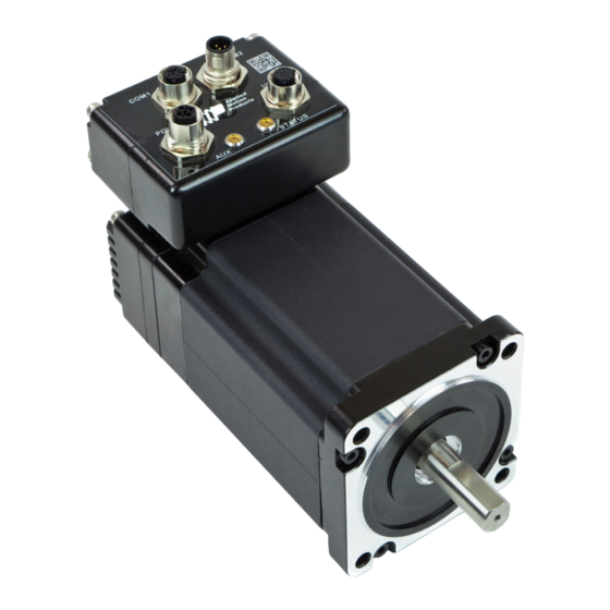
Summary of Contents for Moons' Applied Motion Products TXM34X B Series
- Page 1 TXM34XxB 920-0157 Rev B 10/9/2023...
-
Page 2: Table Of Contents
920-0157 Rev B TXM34XxB Hardware Manual 10/9/2023 Contents 1 Introduction ............................3 1.1 Features ...........................3 1.2 Block Diagram .........................4 1.3 Safety Instructions ........................5 2 Getting Started ..........................6 2.1 Installing Software ........................6 2.2 Mounting the Hardware ......................6 2.3 Choosing a Power Supply .......................6 2.3.1 Supply Voltage .......................7 2.3.2 Auxiliary Supply Voltage (Keep Alive Function) ..............7 2.3.2.1 Power Sequence ....................7... -
Page 3: Introduction
920-0157 Rev B TXM34XxB Hardware Manual 10/9/2023 1 Introduction Thank you for selecting Applied Motion Products TXM34XxB Integrated Motor TruCount™ Absolute Encoder. The TXM line of integrated StepSERVO motors combines servo technology with an integrated motor to create a product with exceptional features and broad capability. We hope our commitment to performance, quality and economy will result in a successful motion control project. -
Page 4: Block Diagram
920-0157 Rev B TXM34XxB Hardware Manual 10/9/2023 1.2 Block Diagram 24 - 70 VDC External Power Supply 12 - 48 VDC 5 Volt DC External Power Supply Power Supply Ethernet RX+, RX-, TX+, TX- Ethernet Ethernet RX+, RX-, TX+, TX- 3.3VDC Internal Voltage... -
Page 5: Safety Instructions
920-0157 Rev B TXM34XxB Hardware Manual 10/9/2023 1.3 Safety Instructions Only qualified personnel should transport, assemble, install, operate, or maintain this equipment. Properly qualified personnel are persons who are familiar with the transport, assembly, installation, operation, and maintenance of motors, and who meet the appropriate qualifications for their jobs. To minimize the risk of potential safety problems, all applicable local and national codes regulating the instal- lation and operation of equipment should be followed. -
Page 6: Getting Started
920-0157 Rev B TXM34XxB Hardware Manual 10/9/2023 2 Getting Started The following items are needed: • a 24 - 70 Volt DC power supply, see the section below “Choosing a Power Supply” for help in choos- ing the right one •... -
Page 7: Supply Voltage
920-0157 Rev B TXM34XxB Hardware Manual 10/9/2023 2.3.1 Supply Voltage The TXM34XxB is designed to give optimum performance at 48 Volts DC. Choosing the voltage depends on the performance needed and motor/drive heating that is acceptable and/or does not cause a drive over-temperature. Higher voltages will give higher speed performance but will cause the TXM34XxB to produce higher tempera- tures. -
Page 8: Keep Alive Recovery With Scl
920-0157 Rev B TXM34XxB Hardware Manual 10/9/2023 2.3.2.3 Keep Alive Recovery with SCL 1. After the main power is removed and the logic remains powered, an undervoltage or internal voltage out of range fault is generated. This alarm displays as a flashing LED pattern and a bit in the alarm code which can be read by the host using the AL command. - Page 9 920-0157 Rev B TXM34XxB Hardware Manual 10/9/2023 It is important to note that the current draw is significantly different at higher speeds depending on the torque load to the motor. Estimating how much current is necessary may require a good analysis of the load the motor will encounter.
- Page 10 920-0157 Rev B TXM34XxB Hardware Manual 10/9/2023 TXM34X3B 24V Power Supply Current Torque Supply Current Full Load Supply Current No Load Speed(RPS) TXM34X3B 48V Power Supply Current Torque Supply Current Full Load Supply Current No Load Speed(RPS) TXM34X3B 70V Power Supply Current Torque Supply Current Full Load...
- Page 11 920-0157 Rev B TXM34XxB Hardware Manual 10/9/2023 TXM34X5B 24V Power Supply Current Torque Supply Current Full Load Supply Current No Load Speed(RPS) TXM34X5B 48V Power Supply Current Torque Supply Current Full Load Supply Current No Load Speed(RPS) TXM34X5B 70V Power Supply Current Torque Supply Current Full Load...
-
Page 12: Connecting The Power Supply
920-0157 Rev B TXM34XxB Hardware Manual8 10/9/2023 TXM34X6B 48V Power Supply Current Torque Supply Current Full Load Full Load Supply Current No Load Speed(RPS) TXM34X6B 70V Power Supply Current Torque Supply Current Full Load Full Load Supply Current No Load Speed(RPS) -
Page 13: Connections
920-0157 Rev B TXM34XxB Hardware Manual 10/9/2023 3 Connections 3.1 Connecting the Power Supply A 3004-331-XX (right angle), 3004-332-XX (straight) power cable is recommended for all TXM34XxB drives. If a user serviceable external fuse is desired, install a 10 amp fast acting fuse in line with the “+” power sup- ply lead. -
Page 14: Connecting To A Pc Using Ethernet
920-0157 Rev B TXM34XxB Hardware Manual 10/9/2023 3.2.5 Connecting to a PC using Ethernet This process requires three steps: Physically connect the motor to the network (or directly to the PC). COM1 COM2 (IN) (OUT) There are 2 Ethernet connectors on the motor labeled COM1 and COM2. - Page 15 920-0157 Rev B TXM34XxB Hardware Manual 10/9/2023 Addresses, Subnets, and Ports Every device on an Ethernet network must have a unique IP address. In order for two devices to communicate with each other, they must both be connected to the network and they must have IP addresses that are on the same subnet.
- Page 16 920-0157 Rev B TXM34XxB Hardware Manual 10/9/2023 Option 1: Connect a Drive to Your Local Area Network If you have a spare port on a switch or router and if you are able to set your drive to an IP address that is compatible with your network, and not used by anything else, this is a simple way to get connected.
- Page 17 920-0157 Rev B TXM34XxB Hardware Manual 10/9/2023 Option 2: Connect a Drive Directly to Your PC 1. Connect one end of a CAT5e STP cable into the LAN card (NIC) on your PC and the other to the drive. You don’t need a special “crossover cable”; the drive will automatically detect the direct connection and make the necessary physical layer changes.
- Page 18 920-0157 Rev B TXM34XxB Hardware Manual 10/9/2023 Option 3: Use Two Network Interface Cards (NICs) This technique allows you to keep your PC connected to your LAN, but keeps the drive off the LAN, pre- venting possible IP conflicts or excessive traffic. 1.
-
Page 19: Inputs And Outputs
920-0157 Rev B TXM34XxB Hardware Manual 10/9/2023 3.3 Inputs and Outputs The TXM34X has three types of inputs: • High speed digital inputs for step & direction commands or encoder following, 5 to 24 volt logic • Low speed digital input for other signals, 5 to 24 volt logic •... - Page 20 TXM34Q/C Hardware Manual 920-0157 Rev B TXM34XxB Hardware Manual 10/9/2023 1 X1/STEP+ 3 X1/STEP- 6 X2/DIR+ 4 X2/DIR- 5 X3+ 8 X3- 0VDC 5-24VDC 7 X7/CW LIMIT+ 10 X7/CW LIMIT- Sensor 5-24VDC 9 X8/CCW LIMIT+ 2 X8/CCW LIMIT- Sensor 100mA Limit 16 +5V Signal 17 AIN...
-
Page 21: Step & Dir Digital Inputs
920-0157 Rev B TXM34XxB Hardware Manual 10/9/2023 3.3.2 STEP & DIR Digital Inputs The TXM34X drives include two high-speed inputs: X1/STEP and X2/DIR. They accept 5 to 24 volt single-ended or differential signals, up to 2 MHz. Typically these inputs connect to an external control- ler that provides step &... -
Page 22: X3/X7/X8 Digital Inputs
920-0157 Rev B TXM34XxB Hardware Manual 10/9/2023 3.3.3 X3/X7/X8 Digital Inputs The X3/X7/X8 inputs are designed for low speed digital input operation between 5 and 24 volts optically isolated differential input. They are normally used for end of travel limit switches. The diagrams below show how to connect the X3/X7/X8 Inputs to various commonly used devices. -
Page 23: Ain Input
920-0157 Rev B TXM34XxB Hardware Manual 10/9/2023 3.3.4 AIN Input The TXM34X drives have an analog input (AIN) which can accept a signal range of 0 to 5 volts. The drive can be configured to operate at a speed or position that is proportional to the analog signal. -
Page 24: Programmable Output Y1/Y2/Y3
920-0157 Rev B TXM34XxB Hardware Manual 10/9/2023 3.3.5 Programmable Output Y1/Y2/Y3 The TXM34X drives feature three optically isolated digital outputs (Y1 to Y3). Y1, Y2 and Y3 share a common terminal YCOM. • Y1 can be set to signal a fault condition. •... -
Page 25: Troubleshooting
920-0157 Rev B TXM34XxB Hardware Manual 10/9/2023 4 Troubleshooting 4.1 Status (STAT) LED Error Codes The TXM34X uses a bi-color LED to indicate status. When the motor is enabled, the LED slowly flashes green. When the LED is solid green, the motor is disabled. Errors are indicated by combinations of red and green flashes as shown below. -
Page 26: Auxiliary Power (Aux) Led
920-0157 Rev B TXM34XxB Hardware Manual 10/9/2023 4.2 Auxiliary Power (AUX) LED If the auxiliary power is connected, this yellow LED will be solid when the power is on. 5 Reference Materials 5.1 Torque-Speed Curves Note: All torque curves are at 10 amps rated continuous current, and 12A for boost torque 24V-10A 48V-10A 72V-10A... - Page 27 920-0157 Rev B TXM34XxB Hardware Manual 10/9/2023 24V-10A 48V-10A 72V-10A TXM34X5B 24V-12A 48V-12A 72V-12A Speed(rps) TXM34X6B 48V-10A 72V-10A 48V-12A 72V-12A Speed(rps)
-
Page 28: Mechanical Outlines
920-0157 Rev B TXM34XxB Hardware Manual 10/9/2023 5.2 Mechanical Outlines TXM34X3B-IP Shaft Loading Data Permissable Shaft Loading (unit: n) Permissa- Model Distance (L) from shaft end (mm) ble Thrust Load TXM34X1B Less than TXM34X3B the motor TXM34X5B mass TXM34X6B... -
Page 29: Technical Specifications
920-0157 Rev B TXM34XxB Hardware Manual 10/9/2023 5.3 Technical Specifications Power Amplifier Amplifier Type Dual H-Bridge, 4 Quadrant Current Control 4 state PWM at 20 KHz TXM34X1B: Up to 2.9 N-m continuous TXM34X3B: Up to 5.6 N-m continuous Output Torque TXM34X5B: Up to 7.2 N-m continuous TXM34X6B: Up to 9.5 N-m continuous Power Supply... -
Page 30: Optional Accessories
920-0157 Rev B TXM34XxB Hardware Manual 10/9/2023 5.4 Optional Accessories Power Supplies Applied Motion Products recommends using the following switching power supplies. Regeneration Clamp P/N: RC880 28.6 When using a regulated power supply you may encounter a problem with regeneration. The kinetic energy caused by regeneration is transferred back to the power supply. -
Page 31: Contact Applied Motion Products
920-0157 Rev B TXM34XxB Hardware Manual 10/9/2023 6 Contact Applied Motion Products Applied Motion Products Inc 18645 Madrone Parkway Morgan Hill, CA 95037 USA Tel (800) 525-1609 www.applied-motion.com...
Need help?
Do you have a question about the Applied Motion Products TXM34X B Series and is the answer not in the manual?
Questions and answers