Table of Contents
Advertisement
Quick Links
CentronicPLUS
SWC541A PLUS
Assembly and Operating Instructions
en
1-channel hand-held transmitter for sun/wind
control, bidirectional
Important information for:
• Fitters / • Electricians / • Users
Please forward accordingly!
These instructions must be kept safe for future reference.
4036 630 263 0 23/11/2022
Becker-Antriebe GmbH
Friedrich-Ebert-Straße 2-4
35764 Sinn/Germany
www.becker-antriebe.com
Advertisement
Table of Contents

Subscribe to Our Youtube Channel
Related Manuals for Becker CentronicPLUS SWC541A PLUS


Summary of Contents for Becker CentronicPLUS SWC541A PLUS
- Page 1 1-channel hand-held transmitter for sun/wind control, bidirectional Important information for: • Fitters / • Electricians / • Users Please forward accordingly! These instructions must be kept safe for future reference. 4036 630 263 0 23/11/2022 Becker-Antriebe GmbH Friedrich-Ebert-Straße 2-4 35764 Sinn/Germany www.becker-antriebe.com...
-
Page 2: Table Of Contents
Table of contents General .................... 3 Licensing information for open source software.......... 3 Warranty .................... 4 Safety instructions ................... 4 Intended use ................... 5 Explanation of displays and buttons ............ 6 Explanation of functions ................ 6 Programming transmitter................ 9 Setting the thresholds ................ 10 Restoring the factory settings of the hand-held transmitter...... 14 Installing the wall bracket................. 15 Changing batteries.................. 15... -
Page 3: General
Written request for the licence texts: Becker-Antriebe will, on request, provide the licence texts for the licensed software being used at cost price, either on a USB stick or a similar data car- rier. Please send an email to the following email address for more information: licenses@becker‑antriebe.com... -
Page 4: Warranty
Warranty Structural modifications and incorrect installation which are not in accordance with these and our other instructions can result in serious injuries, e.g., crush- ing of limbs. Therefore, structural modifications may only be carried out with our prior approval and strictly in accordance with our instructions, particularly the information contained in these Assembly and Operating Instructions. -
Page 5: Intended Use
Intended use The transmitter described in these instructions must only be used indoors for the operation of radio drives and radio control units that are compatible with the CentronicPlus. Attention A safety-relevant function has been provided for the thresholds. Setting the threshold values wrongly can cause damage to the sun protection system. -
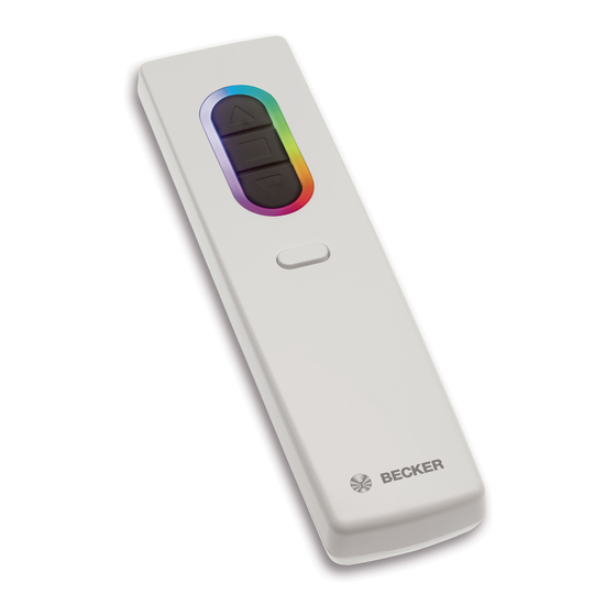
Page 6: Explanation Of Displays And Buttons
Explanation of displays and buttons 1. LED ring function button button 6. Battery compartment button (STOP) programming button button Explanation of functions LED ring Display of: • Confirmations from receiver • Manual / automatic • Threshold / dimming values • Battery status •... - Page 7 Keypad , , • Drive commands • Manual/automatic mode switching • Intermediate position I + II Function button • Identification of the transmitter • Retrieval/setting of thresholds • Retrieval/setting of rain reaction Programming button • Environment scan, as well as selection and programming of receivers •...
- Page 8 Identification of the hand-held transmitter A colour can be assigned to the LED ring of the hand-held transmitter by pressing the function button to make the device easier to identify. The stored colour can be displayed by briefly pressing the function button. If the function button is pressed for longer than 3 seconds, the LED ring flashes briefly.
-
Page 9: Programming Transmitter
Installation key All of the devices operating within an installation must have the same installa- tion key in order to communicate with one another. This key is created on ini- tial commissioning, and is then transmitted to the additional added devices. The installation key is only known to the programmed devices, and cannot be read off. -
Page 10: Setting The Thresholds
Setting the thresholds Setting the thresholds Bring the transmitter as close as possible to the required receiver. Press the programming button for 3 seconds. The transmitter performs a search and the LED ring continuously changes colour. The transmitter then switches to receiver selection and selects the re- ceiver with the best connection quality. - Page 11 Briefly press the programming button to change to the setting mode. ▻ The receiver confirms. ▻ The LED ring of the transmitter slowly pulses light blue. ▻ The receiver now enters dead-man mode. ► The setting mode is now active. If a receiver has not yet been added to the installation (LED ring lights up yellow), it will not be possible to select it in this way.
- Page 12 Briefly press the function button to go to the set- tings for the wind threshold. ▻ The LED ring of the transmitter shows the currently set wind threshold by lighting up red and white. Press the button to adjust the threshold to one of 11 stages (approx.
- Page 13 Press and hold the function button for at least 3 seconds to adopt the set thresholds and to switch to normal mode. ▻ The receiver confirms. ▻ The LED ring of the transmitter goes out. ► This completes the process. When setting the threshold, ensure that no button is pressed.
-
Page 14: Restoring The Factory Settings Of The Hand-Held Transmitter
Restoring the factory settings of the hand-held transmitter When the factory settings of the transmitter are restored, the settings in the receiver, such as run times, thresholds, intermediate positions, etc. as applicable, are not taken into account. Open the cover of the battery compartment and take out the batteries. -
Page 15: Installing The Wall Bracket
Installing the wall bracket • Before installation in the de- sired installation position, check that the transmitter and receiver are functioning prop- Wall bracket erly. • Use two suitable screws to fix the bracket to the wall. Wall bracket Unlocking mechanism mounting plate Changing batteries You will find the appropriate battery type in the "Technical... -
Page 16: Cleaning
Cleaning Only clean the device with a suitable cloth. Do not use aggressive cleaning agents that may damage the surface. Disposal The crossed-out bin symbol on the product indicates that the device is subject to mandatory disposal separate from household waste. This product must be handed over to a collection point for electrical and electronic equipment at the end of its service life. -
Page 17: What To Do If
What to do if...? Problem Remedy Tubular drive/receiver is not re- Insert new batteries into the hand- sponding. held transmitter. Insert batteries into the hand-held transmitter correctly. Reduce distance from receiver. Program transmitter. Check the receiver. LED ring flashes yellow or red 4 Insert new batteries into the trans- times.
Need help?
Do you have a question about the CentronicPLUS SWC541A PLUS and is the answer not in the manual?
Questions and answers