Table of Contents
Advertisement
Quick Links
Centronic SunWindControl
SWC245A-II
Assembly and Operating Instructions
en
5-channel hand-held transmitter for wind
control unit
Important information for:
• Fitters / • Electricians / • Users
Please forward accordingly!
These instructions must be kept safe for future reference.
4033 630 279 0 14/07/2022
Becker-Antriebe GmbH
Friedrich-Ebert-Straße 2-4
35764 Sinn/Germany
www.becker-antriebe.com
Advertisement
Table of Contents

Related Manuals for Becker Centronic SunWindControl SWC245A-II


Summary of Contents for Becker Centronic SunWindControl SWC245A-II
- Page 1 5-channel hand-held transmitter for wind control unit Important information for: • Fitters / • Electricians / • Users Please forward accordingly! These instructions must be kept safe for future reference. 4033 630 279 0 14/07/2022 Becker-Antriebe GmbH Friedrich-Ebert-Straße 2-4 35764 Sinn/Germany www.becker-antriebe.com...
-
Page 2: Table Of Contents
Table of contents General .................... 3 Warranty .................... 3 Safety instructions ................... 4 Intended use ................... 5 Explanation of displays and buttons ............ 6 Explanation of functions ................ 6 Factory default settings ................ 8 Programming the transmitter .............. 9 Installing the wall bracket................. 10 Changing batteries.................. 10 Cleaning.................... 10 Technical data .................. 11... -
Page 3: General
General With this transmitter you are able to control up to 5 sun protection systems via assigned channels, individually or together, and set the threshold value for wind monitoring with the setting tool included. The set threshold applies to all channels. -
Page 4: Safety Instructions
Safety instructions General information • Please keep the instruction manual safe! • Only use in dry rooms. • Only use unmodified original parts from the control unit manufacturer. • Keep children away from control units. • Observe all pertinent country-specific regulations. •... -
Page 5: Intended Use
Intended use The transmitter described in these instructions must only be used indoors for the operation of Centronic-compatible radio drives and radio control units for sun protection systems. Attention A safety-relevant function has been provided for the threshold controller. Setting the threshold value wrongly can cause damage to the sun protection system. -
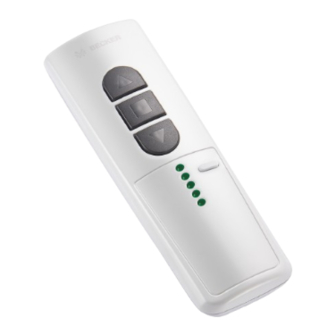
Page 6: Explanation Of Displays And Buttons
Explanation of displays and buttons 1. Setting tool 6. Channel selection button 2. Wind threshold regulator 7. Channel indicator lamps 3. RETRACT button 8. Programming button 4. STOP button 9. Labelling field 5. EXTEND button 10. Type plate Explanation of functions Channel The channel of a transmitter can be programmed into one or more receivers. - Page 7 Channel selection button Up to 5 channels can be selected using the channel selection button. The indi- vidual channels are indicated by the corresponding channel indicator lamp lighting up. If all of the channel indicator lamps light up simultaneously, the central command can be programmed or transmitted. You can make a note of the programmed channel in the la- belling field underneath the transparent film.
-
Page 8: Factory Default Settings
Wind threshold regulator (in connection with a suitable sensor from the controller manufacturer) You set the wind threshold value with this regulator (between about 2 m/s and 22 m/s). The wind threshold value can be adjusted in 11 steps. When slowly turning the regulator, the tubular drive clicks to indicate the setting changes. -
Page 9: Programming The Transmitter
Programming the transmitter Caution Before programming the transmitter, check that the threshold controller is as set at the factory. Make sure when programming the transmitter that you are not in the travel re- gion of the sun protection system. 1) Programming the master transmitter a) Readying the receiver for programming The master transmitter refers to the very first transmitter programmed in a receiver. -
Page 10: Installing The Wall Bracket
Installing the wall bracket • Before installation in the de- sired installation position, Wall bracket check that the transmitter and receiver are functioning prop- erly. Wall bracket Unlocking mechanism mounting • Fix the bracket to the wall with plate the two screws enclosed. Changing batteries You will find the appropriate battery type in the "Technical data"... -
Page 11: Technical Data
Technical data Rated voltage 3 V DC Battery type CR 2430 Degree of protection IP 20 Permissible ambient temperature -10 °C to +55 °C Maximum emitted transmission output ≤ 3 mW Radio frequency 915.3 MHz The maximum transmitter range on and in the building is up to 15 m, and up to 150 m in the open.
Need help?
Do you have a question about the Centronic SunWindControl SWC245A-II and is the answer not in the manual?
Questions and answers