Summary of Contents for Nice BusT4
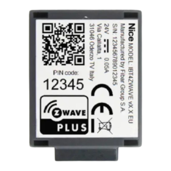
- Page 1 Nice IBT4ZWAVE BusT4 - Z-Wave interface EN - Instructions and warnings for installation and use...
-
Page 2: Warnings And General Precautions
Gate&Door-type Nice automations compatible with the BUS T4 (Opera) protocol. Before proceeding with the product’s installation, make sure to have the following: • 1 Nice automation control unit of the Gate&Door catalogue equipped with BUS T4 connector • 1 Z-Wave smart home controller •... -
Page 3: External Antenna
05. Power the automation’s control unit 06. LEDs on the IBT4ZWAVE will show adding and antenna status (Table 1) 07. Wait for the IBT4ZWAVE to finish initialization sequence (T4 LED flashing green) 08. Add the device to the Z-Wave network; for the relevant procedure see Chapter 4 ADDING TO THE Z-WAVE NETWORK Install the external antenna before powering the device and adding to the Z-Wave network for the device to automatically detect and enable it (use only antennas and cables compliant with technical specification –... -
Page 4: Operation
6.1 - Checking and switching enabled antenna External antenna will be detected and enabled automatically after powering the device (if not added to the Z-Wave network), but you can switch manually between antennas using the following procedure. 01. Press and hold the S1 button 03. -
Page 5: Technical Specifications
The product IBT4ZWAVE is produced by Nice S.p.a. (TV). Warnings: - All technical specifications stated in this section refer to an ambient temperature of 20°C (± 5°C) - Nice S.p.a. reserves the right to apply modifications to the product at any time when deemed necessary, while maintaining the same functionalities and intended use. - Page 6 Table 4 - Association Command Class Group Group Name Profile Max. Nodes Supported Description Lifeline General: Lifeline (0x00: 0x01) Reports the device status to the Z-Wave gateway Table 5 - Multilevel Switch Command Class / Basic Command Class mapping Basic Command Mapped Command Basic Set (Value) Multilevel Switch Set (Value)
-
Page 7: Product Disposal
Table 11 - Configuration Command Class 30. Alarm configuration - 1st slot Description This parameter determines to which alarm frames and how the device should react. The parameters consist of 4 bytes, three most significant bytes are set according to the official Z-Wave protocol specification. Parameter size Default value [0x00, 0x00, 0x00, 0x00] (disabled) - Page 8 PLACE FOR CE DECLARATION...
- Page 9 Nice SpA Oderzo TV Italia www.niceforyou.com info@niceforyou.com...


Need help?
Do you have a question about the BusT4 and is the answer not in the manual?
Questions and answers