Table of Contents
Advertisement
Quick Links
Advertisement
Table of Contents

Subscribe to Our Youtube Channel
Related Manuals for Falcon Mercury 1082 Dual Fuel


Summary of Contents for Falcon Mercury 1082 Dual Fuel
- Page 1 USER GUIDE & INSTALLATION INSTRUCTIONS Mercury 1082 Dual Fuel...
- Page 2 SLOW BAKED LEG OF LAMB METHOD 1. Preheat the oven to 220 ¡C (for a conventional oven), 200 ¡C (for a fan oven) or gas mark 7. 2. Pull the small sprigs off the rosemary branches and set aside with the garlic. 2.
-
Page 3: Table Of Contents
Circuit Diagram Cleaning Your Cooker Technical Data Essential Information Daily Care Cleaning for Spills Hotplate Burners Stainless Steel Main Top Griddle (Optional Extra) Glide-out Grill Control Panel and Oven Doors Ovens Tall Oven Cleaning Table Mercury 1082 Dual Fuel U110241-03A... -
Page 5: Before You Start
1. Before You Start... Your cooker should give you many years of trouble-free Ventilation cooking if installed and operated correctly. It is important CAUTION: The use of a gas cooking appliance results that you read this section before you start, particularly if you in the production of heat and moisture in the room have not used a dual fuel cooker before. -
Page 6: Cooker Care
Always keep combustible materials, e.g. curtains, and DO NOT use water on grease fires and never pick flammable liquids a safe distance away from your cooker. up a flaming pan. Turn the controls off and then smother a flaming pan on a surface unit by covering DO NOT spray aerosols in the vicinity of the cooker the pan completely with a well fitting lid or baking while it is on. -
Page 7: Cooker Overview
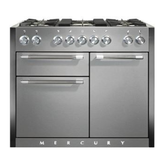
DocAUS.020-0004 - Overview - 110DF - Elan 2. Cooker Overview Fig.2-1 1 0 0 1 0 0 2 2 0 2 2 0 1 4 0 1 4 0 1 8 0 1 8 0 The 1082 dual fuel cooker (Fig.2-1) has the following features: Fig.2-2 5 hotplate burners including 1 wok burner A control panel... -
Page 8: Wok Burner
If, when you let go of the control knob the burner goes out, Fig.2-3 then the FSD has not been bypassed. Turn the control knob to the OFF position and wait for one minute before you try again, this time making sure to hold in the control knob for slightly longer. -
Page 9: Griddle (Optional Extra)
Griddle (Optional Extra) Fig.2-11 The griddle fits over the left-hand pan supports, front to back (Fig.2-11). It is designed for cooking food on directly. DO NOT use pans of any kind on it. The griddle surface is non-stick and metal cooking utensils (e.g. spatulas) will damage the surface. Use heat resistant plastic or wooden utensils. -
Page 10: Ovens
Ovens Fan oven cooking is particularly suitable for baking on several shelves at one time and is a good ‘all-round’ function. It may References to ‘left-hand’ and ‘right-hand’ ovens apply as viewed be necessary to reduce the temperature by approximately from the front of the appliance. - Page 11 Browning Element Function This function uses the element in the top of the oven To thaw small items in the oven without Defrost only. It is a useful function for the browning or heat finishing of pasta dishes, vegetables in sauce, A full cooking function, even heat shepherds pie and lasagne, the item to be browned being Fan oven...
-
Page 12: Accessories
Accessories Fig.2-20 Fig.2-21 Oven Shelves The cooker is supplied with the following: Left-hand Oven 1 standard shelf (Fig.2-20) 1 drop shelf (Fig.2-21) 1 telescopic shelf with runners (Fig.2-22) 1 set of side supports (Fig.2-23) Fig.2-22 Fig.2-23 Right-hand Oven 4 flat cooking shelves (Fig.2-24) 1 plate warming shelf (Fig.2-25) 1 set of side supports (Fig.2-26) Fig.2-24... - Page 13 To Fit the Telescopic Shelf Runners Fig.2-27 With the runner arm in the closed position locate the opening of the upper rear slot onto the side support (Fig.2-27). Do not locate any further than the opening at this point. Lift the front of the runner arm to locate the front slot against the side support (Fig.2-27).
-
Page 14: Cooking Tips
3. Cooking Tips Cooking with a Multi-function Oven General Oven Tips Remember: not all modes are suitable for all food types. The The wire shelves should always be pushed firmly to the back oven cooking times given are intended for a guide only. of the oven. -
Page 15: Cooking Table
DocNo.031-0004 - Cooking table - electric & fan single cavity 4. Cooking Table The oven control settings and cooking times given in the table below are intended to be used Top (T) AS A GUIDE ONLY. Individual tastes may require the temperature to be altered to provide a ArtNo.050-0007 preferred result. -
Page 16: Cleaning Your Cooker
5. Cleaning Your Cooker Essential Information Fig.5-1 Isolate the electricity supply before carrying out any thorough cleaning. Allow the cooker to cool. NEVER use paint solvents, washing soda, caustic ArtNo.311-0028 - Burner head off cleaners, biological powders, bleach, chlorine based bleach cleaners, coarse abrasives or salt. -
Page 17: Griddle (Optional Extra)
Wipe loose debris from main top. Avoid using any abrasive Fig.5-4 cleaners including cream cleaners. For best results use a liquid detergent cleaner. Rinse with cold water and thoroughly dry with a clean, soft cloth. Ensure all parts are dry before repositioning. Griddle (Optional Extra) Always clean the griddle after use. -
Page 18: Control Panel And Oven Doors
Control Panel and Oven Doors Fig.5-8 Avoid using any abrasive cleaners including cream cleaners. For best results, use a liquid detergent. The control panel and control knobs should only be cleaned with a soft cloth wrung out in clean hot soapy water – but take care that no surplus water seeps into the appliance. -
Page 19: Cleaning Table
Cleaning Table Cleaners listed (Table 5-1) are available from supermarkets or electrical retailers as stated. For enamelled surfaces use a cleaner that is approved for use on vitreous enamel. Regular cleaning is recommended. For easier cleaning, wipe up any spillages immediately. Hotplate Part Finish... -
Page 20: Troubleshooting
6. Troubleshooting Hotplate ignition or cooktop burners faulty We do not recommend corrosive or caustic cleaners as these may damage your cooker. Is the power on? Are the sparker (ignition electrode) or burner holes The knobs get hot when I use the oven, can I avoid this? blocked by debris? Yes, this is caused by heat rising from the oven, and heating them up. - Page 21 Oven not coming on Fig.6-1 Is the power on? If not there may be something wrong with the power supply. Is the cooker supply on at the circuit breaker? Have you set a cooking function? Oven temperature getting hotter as the cooker gets older ArtNo.320-0006b -Mercury oven door hinge adjustment If turning the knob down has not worked or only worked for a short time then you may need a new...
-
Page 22: Installation
INSTALLATION Check the appliance is electrically safe and gas sound when you have finished. 7. Installation Dear Installer Provision of Ventilation Before you start your installation, please complete the details This appliance is not connected to a combustion products below, so that, if your customer has a problem relating to evacuation device. - Page 23 INSTALLATION Check the appliance is electrically safe and gas sound when you have finished. You will need the following equipment to complete the Checking the Parts: cooker installation satisfactorily: 5 pan supports Wok cradle • Stability bracket: If the cooker is to be supplied with gas through a flexible hose, a stability bracket or chain MUST be fitted.
-
Page 24: Positioning The Cooker
INSTALLATION Check the appliance is electrically safe and gas sound when you have finished. Positioning the Cooker Fig.7-1 Fig.7-1 and Fig.7-2 show the minimum recommended distance from the cooker to nearby surfaces. 33 mm 33 mm 800 mm The cooker should not be placed on a base. Above hotplate surround should be level with, or above, any adjacent work surface. -
Page 25: Fitting The Flue And Vent
INSTALLATION Check the appliance is electrically safe and gas sound when you have finished. Lowering the Two Rear Rollers Fig.7-5 To adjust the height of the rear of the cooker, first fit a 13 mm spanner or socket wrench onto the hexagonal adjusting nut (Fig.7-5). -
Page 26: Fitting The Side Panels
INSTALLATION Check the appliance is electrically safe and gas sound when you have finished. Fitting the Side Panels Fig.7-9 Fit the two rear side panel brackets onto the rear of the Rear left Rear right cooker (Fig.7-9) and secure. Make sure the brackets are correctly orientated. - Page 27 INSTALLATION Check the appliance is electrically safe and gas sound when you have finished. Fig.7-13 Locating slot Bracket Fig.7-12 Fig.7-14 Fig.7-15 Fig.7-17 Gasket* Fig.7-16 Fig.7-18...
-
Page 28: Fitting The Stability Bracket Or Chain
INSTALLATION Check the appliance is electrically safe and gas sound when you have finished. Fitting the Stability Bracket or Chain Fig.7-19 Unless otherwise stated, a cooker using a flexible gas connector must be secured with a suitable stability device. Stability chain Suitable stability devices are shown in Fig.7-19, Fig.7-20 and Fig.7-21. -
Page 29: Gas Connection
INSTALLATION Check the appliance is electrically safe and gas sound when you have finished. Gas Connection Fig.7-23 This must be in accordance with the relevant standards. Gas inlet block The flexible hose (not supplied with the cooker) must be in accordance with the relevant standards. Hoses may be purchased at most builders’... -
Page 30: Electrical Connection
INSTALLATION Check the appliance is electrically safe and gas sound when you have finished. Electrical Connection Fig.7-24 The cooker must be installed by a qualified electrician, in accordance with all relevant national and local regulations. Note: The cooker must be connected to the correct electrical supply as stated on the voltage label on the cooker, through a suitable cooker control unit incorporating a double-pole 10 mm²... -
Page 31: Circuit Diagram
8. Circuit Diagram P095199 P095199 P028728 br b The connections shown in the circuit diagram are for single-phase. The ratings are for 230 V 50 Hz. Code Description Code Description Code Colour Left-hand multi-function oven control Right-hand fan oven control Blue Left-hand multi-function oven control switch Right-hand fan oven thermostat... -
Page 32: Technical Data
9. Technical Data THE COOKER IS CATEGORY: CatII 2H3+ ; CatII 2E+3+ ; CatII 2L3B/P ; CatII 2E3B/P; CatII 2ELL3B/P ; CatII 2H3B/P . It is supplied set for group H natural gas. A conversion kit from NG to LP is packed with the cooker. INSTALLER: Please leave these instructions with the User. - Page 36 Clarence Street, Royal Leamington Spa, Warwickshire, CV31 2AD, England. Tel: +44 (0) 1926 457400 Fax: +44 (0) 1926 450526 E-mail: consumers@falconappliances.co.uk...
Need help?
Do you have a question about the Mercury 1082 Dual Fuel and is the answer not in the manual?
Questions and answers