Fronius Eco Installation Instructions Manual
Hide thumbs
Also See for Eco:
- Installation instructions manual (38 pages) ,
- Quick start manual (8 pages) ,
- Installation manual

Subscribe to Our Youtube Channel
Related Manuals for Fronius Eco


Summary of Contents for Fronius Eco
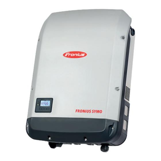
- Page 1 Installation Instructions Fronius Symo 10 - 20 kW Fronius Eco Installation Instructions 42,0426,0175,EN 029-09082023...
-
Page 3: Table Of Contents
String fuses Fronius Eco - string fuses Connection variants on multi-MPP and single-MPP tracker inverters General Multi MPP tracker - Fronius Symo -M inverter Single MPP tracker - Fronius Eco inverter Connecting solar module strings to the inverter Safety General comments regarding PV modules... - Page 4 Overview of DC SPD option Retrofitting the DC SPD‑S option to the Fronius Symo Retrofitting the DC SPD‑M option to the Fronius Symo Retrofitting the DC SPD‑S option to the Fronius Eco Factory-installed DC SPD option wiring Access the Basic menu...
-
Page 5: Installation Location And Position
Installation location and position Explanation of DANGER! safety notices Indicates immediate danger. ▶ If not avoided, death or serious injury will result. WARNING! Indicates a potentially hazardous situation. ▶ If not avoided, death or serious injury may result. CAUTION! Indicates a situation where damage or injury could occur. ▶... -
Page 6: Proper Use/Intended Purpose
Fronius the installation of components that are not distributed or expressly ap- proved by Fronius. Fronius shall not be liable for any damage resulting from such action. No warranty claims will be entertained. Proper use also includes: Carefully reading and obeying all the instructions and all the safety and... -
Page 7: Choice Of Location
2501 to 3000 m = 900 V 3001 to 3400 m = 850 V IMPORTANT! The inverter must not be installed or used at alti- tudes above 3400 m. Fronius Eco: at an altitude of: DCmax 0 to 2000 m = 1000 V... -
Page 8: Installation Position
All inverters are designed to be dust-tight. However, in areas with a heavy build-up of dust, the thermal efficiency may still be impaired by dust forming on the cooling surfaces. Regular clean- ing is necessary in such situations. We therefore recommend not installing the inverter in areas and environments with high dust accumulation. -
Page 9: General Comments Regarding Choice Of Location
Do not install the inverter on a vertical wall or pillar with its con- nection sockets facing upwards. Do not install the inverter overhanging with the connection sock- ets at the top. Do not install the inverter overhanging with the connection sock- ets at the bottom. -
Page 10: Attaching The Mounting Bracket
Attaching the Mounting Bracket Safety WARNING! Danger of residual voltage from capacitors. This may result in an electric shock. ▶ Wait for the capacitors to discharge. The discharge time is indicated on the inverter. CAUTION! Danger due to dirt or water on the terminals and contacts of the inverter's con- nection area. -
Page 12: Fitting The Mounting Bracket To A Wall
Installing the When installing the inverter on a mast mounting brack- or support, Fronius recommends the et on a mast or "Pole Clamp" kit from Rittal GmbH (or- beam der no. SZ 2584.000). This kit enables the inverter to be in- stalled on round or rectangular masts with the following diameters: Æ... -
Page 13: Fitting The Mounting Bracket To Metal Supports
Fitting the NOTE! mounting brack- et to metal sup- When mounted on metal supports, the inverter must not be exposed to rainwa- ports ter or splashing water from the rear. Provide suitable rainwater protection or splash water protection. The mounting bracket must be securely screwed to at least four points. Do not warp or IMPORTANT! When fitting the mounting bracket to the wall, ensure that the deform the... -
Page 14: Connecting The Inverter To The Public Grid (Ac Side)
Connecting the inverter to the public grid (AC side) Safety WARNING! Danger due to incorrect operation and incorrectly performed work. This may result in serious injury and damage to property. ▶ Only qualified staff are authorised to commission your inverter and only within the scope of the respective technical regulations. -
Page 15: Ac Terminals
Immediately connect the cable end to the terminal IMPORTANT!Repeat the procedure if the cable has been disconnected and is to be re-connected. AC terminals Fronius Symo Fronius Eco Ground conductor / earthing L1-L3 Phase conductor Neutral conductor Max. cross-section of each conductor cable: 16 mm²... -
Page 16: Cross Section Of The Ac Cable
This can be ensured, for example, by making it somewhat longer and by laying it in a loop. min. 80°C / 176 °F Fronius Symo... - Page 17 With the Fronius Eco, the three phases and the neutral conductor must be passed through a ferrite ring. The fer- rite ring is supplied with the inverter. The ground conductor (PE) must not be passed through the ferrite ring. Fronius Eco...
-
Page 18: Maximum Fuse Rating On Alternating Current Side
C 80 A Fronius Symo 17.5-3-M 17,500 W C 80 A Fronius Symo 20.0-3-M 20,000 W C 80 A Fronius Eco 25.0-3-M 25,000 W C 80 A Fronius Eco 27.0-3-M 27,000 W C 80 A Note! Local regulations, the electricity retailer or other factors may require a residual- current protective device in the AC connection lead. - Page 19 For this reason, Fronius recommends that a residual-current circuit breaker that is suitable for frequency converters should be used.
-
Page 20: String Fuses
▶ Make sure that the DC side is de-energised before carrying out any work on the inverter fuse holder. String fuses are used in the Fronius Eco to provide additional protection for the solar modules. The short circuit current I and the maximum series string fuse data (e.g. - Page 21 Replacing fuses: CHECK VALUES! Lock Check values!
-
Page 22: Connection Variants On Multi-Mpp And Single-Mpp Tracker Inverters
There are 3 terminals for DC+ per MPP tracker. In total there are six terminals for DC-. In the case of inverters with single MPP trackers like the Fronius Eco, there is 1 DC input (MPP tracker) available. The number of PV modules per string connec- tion should be the same. - Page 23 DC- terminal is not neces- sary because it is jumpered internally. DC Con Kit 25 The Fronius DC Con Kit 25 (4,251,015) can be used to connect a solar module string with a cross-section of up to 25 mm² to the inverter.
- Page 24 Kit 25: 5.5 Nm / 50 lb-in DC Con Kit 35 The Fronius DC Con Kit 35 (4,251,029) can be used to connect a PV string with a cross-section of up to 35 mm² to the inverter. Set the MPP tracker 2 to "Off" during initial commissioning.
-
Page 25: Single Mpp Tracker - Fronius Eco Inverter
DC+2 DC Con Kit 25 The Fronius DC Con Kit 25 (4,251,015) can be used to connect a solar module string with a cross-section of up to 25 mm² to the inverter. By using the DC Con Kit 25, the DC strings of the connected DC lines are equally distributed to both inputs. - Page 26 Kit 25: 5.5 Nm / 50 lb-in DC Con Kit 35 The Fronius DC Con Kit 35 (4,251,029) can be used to connect a solar module string with a cross-section of up to 35 mm² to the inverter. By using the DC Con Kit 35, the DC strings of the connected DC lines are divided equally between both inputs.
-
Page 27: Connecting Solar Module Strings To The Inverter
Fronius Symo: The maximum amperage when connecting to a single DC ter- minal is 33 A. ▶ Fronius Eco: The maximum amperage when connecting to a single DC ter- minal is 15 A. ▶ Connect the DC+ and DC- cables to the DC+ and DC- terminals on the in- verter, taking care to ensure that the polarity is correct. -
Page 28: General Comments Regarding Pv Modules
Exact values for sizing the solar modules can be obtained using suitable cal- culation tools, such as the Fronius Solar.creator (creator.fronius.com). IMPORTANT! Before connecting up the solar modules, check that the voltage for the solar modules specified by the manufacturer corresponds to the actual measured voltage. -
Page 29: Connecting Aluminium Cables
When installed between 0 and 2000 m above sea level: 1000 V ▶ When installed between 2001 and 2500 m above sea level: 950 V ▶ the Fronius Eco must not be installed at an altitude exceeding 2500 m above sea level... -
Page 30: Connecting The Solar Module Strings To The Inverter
(e.g. if there are 2 DC cables, then break out 2 recesses). strings to the in- verter IMPORTANT! Fronius Eco: check the string fuses used (type and rating) before connecting the solar module strings to the inverter. 2.5 - 10 mm²... - Page 31 IMPORTANT! Observe the torque val- ues marked on the side underneath the terminals.
- Page 32 If DC cables are laid over the shaft of the DC main switch or across the con- nection block of the DC main switch, they may be damaged when the invert- er is swung in or they may even prevent the inverter from being swung in.
-
Page 33: Data Communication
To cater for this eventuality, a suitable blanking cover (item number 42,0405,2094) is available from Fronius as an option. IMPORTANT! If data communication cables are wired into the inverter, observe the following points:... - Page 34 IMPORTANT! Observe the ESD guidelines when handling option cards. IMPORTANT! Only one Fronius Datamanager in master mode is permitted per Fronius Solar Net ring. Switch any other Fronius Datamanagers to slave mode or remove them. Seal off the unoccupied option card slot by replacing the cover (item number 42,0405,2094);...
-
Page 36: Attaching The Inverter To The Mounting Bracket
Attaching the inverter to the mounting bracket Attaching the in- WARNING! verter to the mounting brack- Danger from inadequate ground conductor connection. This can result in serious injury and damage to property. ▶ The housing screws provide a suitable ground conductor connection for earthing the housing and must NOT be replaced by any other screws that do not provide a reliable ground conductor connection. -
Page 39: Attaching The Metall Bracket
Attaching the With the Fronius Eco, a metal bracket metall bracket included in the scope of delivery must also be fitted to the device. This metal bracket is required for compliance with EMC (electromagnetic compatibility) regulations. -
Page 40: Starting For The First Time
Starting for the first time Starting the in- WARNING! verter for the first time Danger due to incorrect operation and incorrectly performed work. This can result in serious injury and damage to property. ▶ Only qualified personnel are authorised to commission your inverter and only within the scope of the respective technical regulations. - Page 41 * Country setup examples The available country setups may change during a software update. Therefore, the following list may not exactly match the display on the inverter. 50Hz International 50 Hz DE2P Deutschland (> 4,6 kVA) Italia ≤ 11,08 kVA 2019 60Hz International 60 Hz - cosPhi(P) 0,9 Italia >...
- Page 42 B A S I C M P P T R A C K E R 2...
-
Page 43: Notes Regarding Software Updates
Notes regarding software updates Notes regarding If the inverter is supplied with a USB software up- flash drive, the inverter software must dates be updated as soon as the inverter has been commissioned: Plug the USB flash drive into the data communication area of the in- verter Open the Setup menu... -
Page 44: Usb Stick As A Data Logger And For Updating Inverter Software
The file must not be deleted separately. Only delete all of the files (sys, fld, csv) at one time. DALO.fld log file: A log file for reading the data in the Fronius Solar.access software. Further details on the Fronius Solar.access software can be found in the "DATCOM Details" operating instructions at http://www.fronius.com DATA.csv log file:... -
Page 45: Data Volume And Storage Capacity
Structure of the CSV file: Inverter no. Inverter type (DATCOM code) Logging interval in seconds Energy in watts per second, relative to the logging interval Inductive reactive power Capacitive reactive power Average values during the logging interval (AC voltage, AC current, DC voltage, DC current) Additional information Data volume and... -
Page 46: Buffer Memory
ON - see the Datamanager 2.0 Operating Instructions, section "Setting and displaying the menu items", "Viewing and adjusting parameters in the DATCOM menu item"). On the Fronius Eco or Fronius Symo 15.0-3 208, the buffer memory also func- tions with just a DC supply. Suitable USB... -
Page 47: Usb Stick For Updating The Inverter Software
USB symbol on the inverter display, e.g. in display mode "NOW": If the inverter detects a USB flash drive, the USB symbol will appear in the top right corner of the display. When inserting a USB flash drive, check whether the USB symbol is dis- played (it may also flash). -
Page 48: Notes Regarding Maintenance
Maintenance IMPORTANT! When installed outdoors in a horizontal position: once a year, check that all screw joints are tight! Maintenance and servicing may only be carried out by Fronius-trained service technicians. Cleaning Clean the inverter as required with a damp cloth. -
Page 49: Australian Conduits
Australian Conduits Tightly sealing Ensure that the conduits are tightly sealed. the conduits Seal conduits NOTE! Condensation within the conduits can damage the inverter or components of the photovoltaic systems. To avoid undesirable air circulation and condensation in the conduits: ▶... -
Page 50: Serial Number Sticker For Customer Use
Serial Number Sticker for Customer Use Serial number The serial number of the inverter is sticker for cus- located on the rating plate on the bot- tomer use tom of the inverter. Depending on the installation position of the inverter, the serial number can be difficult to access or read, e.g. -
Page 51: Dc Spd Option
*Note: The PV current is displayed distorted by the hardware topology used. Retrofitting the The DC cables can be connected to the DC terminals without ferrules. DC SPD‑S option to the Fronius To retrofit the DC SPD-S option to the inverter: Symo... -
Page 52: Retrofitting The Dc Spd-M Option To The Fronius Symo
Earthing can also be established via the connec- ted AC cable. Retrofitting the The DC cables can be connected to the DC terminals without ferrules. DC SPD‑M op- tion to the Froni- us Symo... - Page 53 To retrofit the DC SPD-M option to the inverter: Earthing can also be established via the connec- ted AC cable.
-
Page 54: Retrofitting The Dc Spd-S Option To The Fronius Eco
Retrofitting the The DC cables can be connected to the DC terminals without ferrules. DC SPD‑S option to the Fronius... -
Page 56: Factory-Installed Dc Spd Option Wiring
Earthing can also be established via the connec- ted AC cable. max. 5,5mm² Factory-in- When the DC SPD option is pre-installed at the factory, the following wiring stalled DC SPD must be performed: option wiring The M16 cable gland is included in the scope of delivery. Earthing can also be established via the connected AC cable. -
Page 57: Access The Basic Menu
Earthing can also be established via the connected AC cable. DC SPD - S option Access the Basic Press the "Menu” button menu The menu level appears. Press the unassigned "Menu / Esc" key 5 times Code" is displayed in the "CODE" "Access menu;... -
Page 58: Settings In The Basic Menu
The second digit flashes. A c c e s s C o d e Repeat steps 3 and 4 for the second, third, fourth and fifth digits of the access code until... the selected code starts flashing. Press the "Enter" button The Basic menu appears. - Page 59 * Select the appropriate setting depending on the application.
-
Page 60: Dc-Plug +- Pair Mc4 Option
DC-plug +- pair MC4 option General The inverter can be ordered with the DC-plug +- pair MC4 option. Unused connections must be covered with a cover plate. The cover plates can be ordered using the following item numbers: MC30A DC+: 43,0003,0880 MC30A DC-: 43,0003,0879... - Page 61 The scope of delivery for the inverter with the DC-plug +- pair MC4 option includes a label with a cable overview. This label can be positioned on the in- verter in a suitable place.
Need help?
Do you have a question about the Eco and is the answer not in the manual?
Questions and answers